Shallow-water wave theory
Contents
- 1 Introduction
- 2 Wave generation
- 3 Small amplitude wave theory
- 3.1 Derivation of the Airy Wave equations
- 3.2 Numerical Solution of the Wave Dispersion Equation
- 3.3 Water particle velocities, accelerations and paths
- 3.4 Pressure variation induced by wave motion
- 3.5 The influence of water depth on wave characteristics
- 3.6 Group velocity and energy propagation
- 3.7 Radiation Stress (Momentum Flux)
- 4 Wave transformation and attenuation processes
- 4.1 Refraction
- 4.2 Shoaling
- 4.3 Combined refraction and shoaling
- 4.4 Bathymetry effects on Refraction
- 4.5 Shoaling and refraction of directional wave spectra
- 4.6 Seabed Friction
- 4.7 Wave-Current Interaction
- 4.8 Wave Reflection
- 4.9 Wave reflection coefficients
- 4.10 Wave reflection due to refraction
- 4.11 Wave Diffraction
- 4.12 Combined refraction and diffraction
- 5 Finite amplitude waves
- 6 Wave forces
- 7 Surf Zone Processes
- 8 Further reading
- 9 Related articles
- 10 References
Introduction
This article explains some theories of periodic progressive waves and their interaction with shorelines and coastal structures. The first section provides a descriptive overview of the generation of wind waves, their characteristics, the processes which control their movement and transformation. The following sections describe some aspects of wave theory of particular application in coastal engineering. Some results are quoted without derivation, as the derivations are often long and complex. The interested reader should consult the references provided for further details.
It should be noted that this article has been abstracted from the text book “Coastal Engineering: Processes, Theory and Design Practice” 2nd edn (2012) and 3rd edn (in press)[1], with the permission of Spon Press.
Wave generation
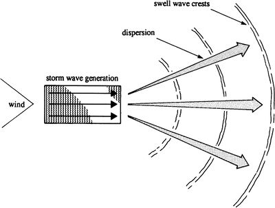
Ocean waves are mainly generated by the action of wind on water. The waves are formed initially by a complex process of resonance and shearing action, in which waves of differing wave height, length, period are produced and travel in various directions. Once formed, ocean waves can travel for vast distances, spreading in area and reducing in height, but maintaining wavelength and period as shown in Figure 1.
In the storm zone generation area high frequency wave energy (e.g. waves with small period) is both dissipated and transferred to lower frequencies. Waves of differing frequencies travel at different speeds and therefore outside the storm generation area the sea state is modified as the various frequency components separate. The low frequency waves travel more quickly than the high frequency waves resulting in a swell sea condition as opposed to a storm sea condition. This process is known as dispersion. Thus wind waves may be characterised as irregular, short crested and steep containing a large range of frequencies and directions. On the other hand swell waves may be characterised as fairly regular, long crested and not very steep containing a small range of low frequencies and directions.
As waves approach a shoreline, their height and wavelength are altered by the processes of refraction and shoaling before breaking on the shore. Once waves have broken, they enter what is termed the surf zone. Here some of the most complex transformation and attenuation processes occur, including generation of cross and longshore currents, a set-up of the mean water level and vigorous sediment transport of beach material. Some of these processes are evident in Figure 2.
Where coastal structures are present, either on the shoreline or in the nearshore zone, waves may also be diffracted and reflected resulting in additional complexities in the wave motion. Figure 3 shows a simplified concept of the main wave transformation and attenuation processes which must be considered by coastal engineers in designing coastal defence schemes.
Additionally, the existence of wave groups are of considerable significance as they have been shown to be responsible for the structural failure of some maritime structures designed using the traditional approach. The existence of wave groups also generates secondary wave forms of much lower frequency and amplitude called bound longwaves (see Infragravity waves). Inside the surf zone these waves become separated from the 'short' waves and have been shown to have a major influence on sediment transport and beach morphology producing long and cross shore variations in the surf zone wave field.
Small amplitude wave theory
The earliest mathematical description of periodic progressive waves is that attributed to Airy in 1845. Airy wave theory is strictly only applicable to conditions in which the wave height is small compared to the wavelength and the water depth. It is commonly referred to as linear or first order wave theory, because of the simplifying assumptions made in its derivation.
Derivation of the Airy Wave equations
The Airy wave was derived using the concepts of two-dimensional ideal fluid flow. This is a reasonable starting point for ocean waves, which are not greatly influenced by viscosity, surface tension or turbulence.
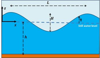
Figure 4 shows a sinusoidal wave of wavelength [math]L[/math], height [math]H[/math] and period [math]T[/math], propagating on water with undisturbed depth [math]h[/math]. The variation of surface elevation with time, from the still water level, is denoted by [math]\eta[/math] (referred to as excursion) and given by
[math] \eta =\Large\frac{H}{2}\normalsize \cos \left\{2\pi \left(\Large\frac{x}{L}\normalsize -\Large\frac{t}{T}\normalsize \right)\right\} = \Large\frac{H}{2}\normalsize \cos ( kx -\omega t ), \qquad (3.1)[/math]
where [math]t[/math] is time and [math]x[/math] is the distance measured along the horizontal axis, which is chosen aligned with the wave propagation direction, the wave number is [math]k = 2\pi / L[/math] and the wave angular frequency is [math]\omega=2 \pi / T[/math]. The wave celerity, the speed [math]c[/math], is given by [math] c= L/T = \omega / k [/math].
We consider frictionless wave propagation. The wave equations then read
Momentum balance horizontal [math]x-[/math]direction: [math] \Large\frac{\partial u }{\partial t}\normalsize + u \Large\frac{\partial u}{\partial x}\normalsize + w \Large\frac{\partial u}{\partial z}\normalsize + \Large\frac{1}{\rho}\frac{\partial p}{\partial x}\normalsize = 0 , \qquad (3.2)[/math]
Momentum balance vertical [math]z-[/math]direction: [math] \Large\frac{\partial w }{\partial t}\normalsize + u \Large\frac{\partial w}{\partial x}\normalsize + w \Large\frac{\partial w}{\partial z}\normalsize + \Large\frac{1}{\rho}\frac{\partial p}{\partial z}\normalsize = - g , \qquad (3.3) [/math]
Continuity equation: [math] \Large\frac{\partial u }{\partial x}\normalsize + \Large\frac{\partial z}{\partial z}\normalsize = 0 . \qquad (3.4)[/math]
Symbols: [math]u=[/math] horizontal orbital velocity component, [math]w=[/math] vertical orbital velocity component, [math]p=[/math] pressure, [math]\rho=[/math] water density, and [math]z=[/math] vertical coordinate (upward positive), [math]z=-h[/math] at the seabed and [math]z=\eta[/math] at the water surface.
The depth [math]h[/math] is assumed spatially uniform. This is a reasonable assumption if spatial variations of the depth are very small over distances of the order of the wave orbital excursion [math]|dh/dx| \lt \lt h / (\overline{|u|} T)[/math]. The overline stands for averaging over the wave period.
The assumption of frictionless flow is a reasonable approximation for most of the water column but does not hold in the wave boundary layer close to the seabed. However, this layer is generally thin, because frequent switching of wave orbital velocity prevents the development of large eddies that span a significant portion of the water column. Frictionless flow implies that the water motion can be considered irrotational, [math]\partial u / \partial z = \partial w / \partial x[/math]. So we have potential flow that can be described by the velocity potential [math]\phi[/math]:
[math]u=\Large\frac{\partial \phi }{\partial x}\normalsize , \quad w=\Large\frac{\partial \phi }{\partial z}\normalsize. \qquad (3.5)[/math]
Equation (3.3) can now be integrated from [math]z[/math] to the surface [math]z=\eta[/math], where the pressure [math]p[/math] vanishes:
[math] \Large\frac{\partial \phi}{\partial t}\normalsize + \Large\frac{1}{2}\normalsize \Bigg( \Big( \Large\frac{\partial \phi}{\partial x}\normalsize \Big)^2+ \Big(\Large\frac{\partial \phi}{\partial z}\normalsize \Big)^2) \Bigg) + \Large\frac{1}{\rho}\normalsize p + g z = \Bigg[ \Large\frac{\partial \phi}{\partial t}\normalsize + \Large\frac{1}{2}\normalsize \Bigg( \Big( \Large\frac{\partial \phi}{\partial x}\normalsize \Big)^2+ \Big(\Large\frac{\partial \phi}{\partial z}\normalsize \Big)^2) \Bigg) \Bigg]_{z=\eta} + g \eta = f(t). \qquad (3.6) [/math]
The right hand side of this equation can be set equal to zero, because [math]f(t)[/math] can be incorporated in the potential [math]\phi(x,z,t)[/math] without modifying the wave equations. Equation (3.1) represents the surface solution to the Airy wave equations. The derivation of the Airy wave equations starts from the continuity for irrotational flow of an ideal fluid, which is the Laplace equation:
[math]\Large\frac{\partial u}{\partial x}\normalsize +\Large\frac{\partial w}{\partial z}\normalsize =0=\Large\frac{\partial ^{2} \phi }{\partial x^{2}\normalsize }+\Large\frac{\partial ^{2} \phi }{\partial z^2}\normalsize . \qquad (3.7)[/math]
A solution for [math]\phi[/math] is sought which satisfies the Laplace equation throughout the body of the flow. Additionally this solution must satisfy the boundary conditions at the bed and on the surface. At the bed assumed horizontal, the vertical velocity w must be zero. At the surface, any particle on the surface must remain on the surface, hence
[math]w=\Large\frac{\partial \eta }{\partial t}\normalsize +u\Large\frac{\partial \eta }{\partial x}\normalsize, \quad z=\eta(x,t) . \qquad (3.8)[/math]
Making the assumptions that [math]H \ll L[/math] and [math]H \ll h[/math] results in the linearised boundary conditions (in which the smaller, higher order and product terms are neglected). The resulting kinematic and dynamic boundary equations are then applied at the still water level, given by,
[math]\Large\frac{\partial \phi }{\partial z}\normalsize =\Large\frac{\partial \eta }{\partial t}\normalsize, \quad g\eta +\Large\frac{\partial \phi }{\partial t}\normalsize =0 , \quad z=0 . \qquad (3.9)[/math]
Solving the Laplace equation (3.7) with the linear boundary conditions at the surface (3.1, 3.9) and the seabed, [math]\Large\frac{\partial \phi }{\partial z}\normalsize (z=-h) =0[/math], is straightforward. The solution is given by
[math]\phi (x,z,t) = \Large\frac{gH}{2 \omega} \frac{\cosh k(h+z)}{\cosh kh}\normalsize \sin (k x- \omega t) , \qquad (3.10)[/math]
with
[math]\omega ^{2} =gk\tanh \left(kh\right) . \qquad (3.11) [/math]
The wave celerity is given by
[math]c = \omega / k = (g / \omega) \tanh (kh) , \qquad (3.12) [/math]
Equation (3.11) is known as the wave dispersion equation.
Numerical Solution of the Wave Dispersion Equation
In order to solve the dispersion equation from first principles it is first necessary to solve the wave dispersion equation for [math]k=2 \pi / L[/math] in any depth [math]h[/math]. This may be done by substituting in Equation (3.12) successive estimates of [math]L[/math] starting with an initial estimate [math]L=L_0[/math] into the [math]\tan (kh)[/math] term. A more efficient technique is described by Goda [2], based on Newton's method, given by
[math]x_{2} =x_{1} -\Large\frac{ x_1 - D \coth x_1 }{1+D ({\coth} ^2 x_1 - 1)}\normalsize , \qquad (3.13)[/math]
where [math]x=kh, \; D=k_0 h=2 \pi h/ L_0[/math] and the best estimate for the initial value is [math]x_1=D , \; D \ge 1 ; \quad x_1=D^{1/2}, \; D \lt 1 . [/math] This provides an absolute error of less than 0.05 [math]\% [/math] after three iterations.
A direct solution was derived by Hunt [3], given by
[math]\Large\frac{gh}{c^{2} }\normalsize =D+\Large\frac{1}{1+0.6522D+0.4622D^{2} +0.0864D^{4} +0.0675D^{5}}\normalsize , \qquad (3.14)[/math]
where [math]D = k_0 h[/math] , which is accurate to 0.1 [math]\%[/math] for [math]0\lt D\lt \infty[/math] .
Water particle velocities, accelerations and paths
The equations for the horizontal, [math]u[/math], and vertical, [math]w[/math], velocities of a particle at a mean depth [math]-z[/math] below the still water level may be determined from [math]\partial \phi / \partial x[/math] and [math]\partial \phi / \partial z[/math] respectively. The corresponding local accelerations, [math]a_x[/math] and [math]a_z[/math], can then be found from [math]\partial u / \partial t[/math] and [math]\partial w / \partial t [/math].
Finally the horizontal, [math]\xi [/math], and vertical, [math]\zeta[/math], displacements can be derived by integrating the respective velocities over a wave period. The resulting equations are given by
[math]\xi =-\Large\frac{H}{2}\normalsize \left[\Large\frac{\cosh \left\{k\left(z+h\right)\right\}}{\sinh kh}\normalsize \right] \sin (kx - \omega t) , \qquad (3.15a) [/math]
[math]u=\Large\frac{\omega H}{2}\normalsize \left[\Large\frac{\cosh \left\{k\left(z+h\right)\right\}}{\sinh kh}\normalsize \right] \cos (kx - \omega t), \qquad (3.15b) [/math]
[math]a_{x} =\Large\frac{\omega^2 H}{2}\normalsize \left[\Large\frac{\cosh \left\{k(z+h)\right\}}{\sinh kh}\normalsize \right] \sin (kx - \omega t) , \qquad (3.15c) [/math]
[math]\zeta =\Large\frac{H}{2}\normalsize \left[\Large\frac{\sinh \left\{k\left(z+h\right)\right\}}{\sinh kh}\normalsize \right] \cos (kx - \omega t) , \qquad (3.15d) [/math]
[math]w=\Large\frac{\omega H}{2}\normalsize \left[\Large\frac{\sinh \left\{k\left(z+h\right)\right\}}{\sinh kh}\normalsize \right] \sin (kx - \omega t), \qquad(3.15e) [/math]
[math]a_{z} =\Large\frac{-\omega^2 H}{2}\normalsize \left[\Large\frac{\sinh \left\{k\left(z+h\right)\right\}}{\sinh kh}\normalsize \right] \cos (kx - \omega t) . \qquad (3.15f) [/math]
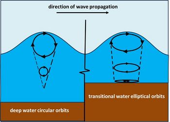
All the equations have three components. The first is a magnitude term, the second describes the variation with depth and is a function of relative depth and the third is a cyclic term containing the phase information. Equations (3.15a) and (3.15e) describe an ellipse, which is the path line of a particle according to linear theory. Equations (3.15b,c) and (3.15e,f) give the corresponding velocity and accelerations of the particle as it travels along its path. The vertical and horizontal excursions decrease with depth, the velocities are 90[math]^{\circ}[/math] out of phase with their respective displacements and the accelerations are 180[math]^{\circ}[/math] out of phase with the displacements. These equations are illustrated graphically in Figure 5.
Readers who wish to see a full derivation of the Airy wave equations are referred to Sorensen [4] and Dean and Dalrymple [5], in the first instance, for their clarity and engineering approach.
Pressure variation induced by wave motion
The equation for pressure variation under a wave is derived by substituting the expression for velocity potential into the unsteady Bernoulli equation (3.6). Neglecting terms of order O[(H/h)^2] the result is
[math]p=-\rho gz+\rho g\Large\frac{H}{2}\normalsize \cos (kx-\omega t)\Large\frac{\cosh \left\{k(h+z)\right\}}{\cosh kh}\normalsize=-\rho gz+\rho g\eta K_{p} (z) , \qquad (3.16) [/math]
valid at or below the still water level, where [math]K_p (z) [/math] is known as the pressure attenuation factor, given by
[math]K_{p} (z)=\Large\frac{\cosh \left\{k(h+z)\right\}}{\cosh kh}\normalsize \qquad (3.17)[/math].
A more precise formula is: [math]\qquad K_{p} (z)=\Large\frac{\cosh(k(h+z))}{\cosh(k(h+\eta))}\normalsize ,\qquad (3.18) [/math]
see the Discussion page.
The pressure attenuation factor reduces to zero at the deep water limit (ie [math]h/L \geq 0.5[/math]). At any depth ([math]-z[/math]) under a wave crest, the pressure is a maximum and comprises the static pressure, [math]p_0=-\rho g z[/math], plus the dynamic pressure, [math]\rho gH K_{p} (z) /2 [/math]. The reason why it is a maximum under a wave crest is because it is at this location that the vertical particle accelerations are at a maximum and are negative. The converse applies under a wave trough.
Pressure sensors located on the seabed can therefore be used to measure the wave height, provided they are located in the transitional water depth region. The wave height can be calculated from the pressure variation by calculating [math]K_p (z) [/math] and subtracting the hydrostatic pressure (mean value of recorded pressure). This requires the solution of the wave dispersion equation for the wavelength in the particular depth, knowing the wave period. This is easily done for a simple wave train of constant period. However, in a real sea comprising a mixture of wave heights and periods, it is first necessary to determine each wave period present (by applying Fourier analysis techniques). Also, given that the pressure sensor will be located in a particular depth, it will not detect any waves whose period is small enough for them to be deep-water waves in that depth.
The influence of water depth on wave characteristics
Deep water
The particle displacement Equations (3.15a) and (3.15d) describe circular patterns of motion in (so-called) deep water. At a depth ([math]-z=L/2[/math]), the diameter is only 4[math]\%[/math] of the surface value and this value of depth is normally taken as the lower limit of deep water waves. Such waves are unaffected by depth, and have little or no influence on the seabed.
For [math]h / L\ge 0.5, \quad \tanh (kh) \approx 1[/math]. Hence Equation (3.12) reduces to
[math] c_{0} = gT / 2 \pi = (g L_0 / 2 \pi )^{1/2} , \qquad (3.19) [/math]
where the subscript 0 refers to deep water. Thus, the deep water wave celerity and wavelength are determined solely by the wave period.
Shallow Water
For [math]h/L \le 0.04, \quad \tanh (kh) \approx 2\pi h /L [/math]. This is normally taken as the upper limit for shallow water waves. Hence Equation (3.11) reduces to [math]c=ghT/L[/math] and substituting this into Equation (3.12) gives [math]c=\sqrt{gh} [/math]. Thus, the shallow water wave celerity is determined by depth, and not by wave period. Hence shallow water waves are not frequency dispersive whereas deep-water waves are.
Transitional Water
This is the zone between deep water and shallow water, i.e. [math]0.5 \gt h/L\gt 0.04 [/math]. In this zone [math]\tanh(kh)\lt 1[/math], hence
[math]c=\Large\frac{gT}{2\pi }\normalsize \tanh \left(kh\right)=c_{0} \tanh \left(kh\right)\lt c_{0} \qquad (3.20)[/math].
This has important consequences, exhibited in the phenomena of refraction and shoaling. In addition, the particle displacement equations show that, at the sea bed, vertical components are suppressed so only horizontal displacements now take place (see Figure 5). This has important implications regarding sediment transport.
Group velocity and energy propagation
The energy contained within a wave is the sum of the potential, kinetic and surface tension energies of all the particles within a wavelength and it is quoted as the total energy per unit area of the sea surface. For Airy waves, the kinetic [math]EK= ½ \rho \overline{\int_{-h}^{\eta} (u^2+w^2) dz}[/math] and potential energy [math]EK = ½ \rho g \overline{\eta^2}[/math] are equal, [math]EK = EP =\rho gH^2 L/16[/math]. Hence, the energy ([math]E[/math]) per unit area of ocean is (ignoring surface tension energy which is negligible for ocean waves)
[math]E=\rho gH^{2} /8 . \qquad (3.21)[/math]
This is a considerable amount of energy. For example, a (Beaufort) Force 8 gale blowing for 24 h will produce a wave height in excess of 5 m, giving a wave energy exceeding 30 kJ/m2.
One might expect that wave power (or the rate of transmission of wave energy) would be equal to wave energy times the wave celerity. This is incorrect, and the derivation of the equation for wave power leads to an interesting result which is of considerable importance. Wave energy is transmitted by individual particles which possess potential, kinetic and pressure energy. Summing these energies and multiplying by the particle velocity in the [math]x[/math]-direction for all particles in the wave gives the rate of transmission of wave energy or wave power ([math]P[/math]), and leads to the result (for an Airy wave)
[math]P=\Large\frac{\rho gH^{2} }{8}\normalsize \Large\frac{c}{2}\normalsize \left(1+\Large\frac{2kh}{\sinh 2kh}\normalsize \right) = E c_{g} , \qquad (3.22) [/math]
where [math]c_g[/math] is the wave group celerity, given by
[math] c_{g} =\Large\frac{c}{2}\normalsize \left(1+\Large\frac{2kh}{\sinh 2kh}\normalsize \right) . \qquad (3.23) [/math].
In deep water ([math]h/L \gt 0.5[/math]) the group wave velocity [math]c_g = c/2[/math], and in shallow water [math]c_g = c[/math]. Hence, in deep water wave energy is transmitted forward at only half the wave celerity.
The term wave group celerity refers to the alternation of groups of large and small waves, which is a common characteristic of the irregular wave fields occurring in ocean and coastal waters. Irregular waves are dealt with in the article Statistical description of wave parameters and wave groups and infragravity waves in the article Infragravity waves.
Radiation Stress (Momentum Flux)
The momentum balance equation (3.2) can be cast in the form
[math] \Large\frac{\partial}{\partial t}\normalsize \int_{-h}^{\eta} u dz + \Large\frac{\partial}{\partial x}\normalsize \int_{-h}^{\eta} u^2 dz + \Large\frac{1}{\rho}\frac{\partial}{\partial x}\normalsize \int_{-h}^{\eta} p dz = 0 , \qquad (3.24)[/math]
as can be shown by using equations (3.4), (3.5) and (3.8). Wave motion is periodic, but the nonlinear terms in this equation drive a net mean flow [math] \overline{u} = \overline{\int_{-h}^{\eta} udz} / (h+ \overline{\eta}) [/math] and a mean water surface slope [math]\overline{\partial \eta / \partial x}[/math]. The overline represents averaging over the wave period. To ensure the approximate validity of equation (3.24) we assume that the net mean flow and mean surface slope are small compared to the wave orbital flow and the wave steepness [math]H/L[/math], respectively. However, a bed friction term [math]\overline{\tau}^{(x)}_b[/math] has to be added in order to balance the acceleration of the net flow by the nonlinear terms. The net mean flow and mean surface slope appear explicitly in equation (3.24) by averaging over the wave period,
[math] \rho (h+ \overline{\eta}) \Large\frac{\partial \overline{u}}{\partial t}\normalsize + \Large\frac{\partial S_{XX}}{\partial x}\normalsize = - \rho g (h + \overline{\eta}) \Large\frac{\partial \overline{\eta}}{\partial x}\normalsize - \overline{\tau}^{(x)}_b , \qquad (3.25)[/math]
where [math]S_{XX}[/math] is the radiation stress defined by
[math]S_{XX} =\overline{\int _{-h}^{\eta } (p+\rho u^{2} )dz } - \int _{-h}^{\overline{\eta}} p_0 dz . \qquad (3.26)[/math]
The hydrostatic pressure term [math]p_0 = \rho g (\overline{\eta} - z)[/math] has been set apart so that equation (3.25) expresses the momentum balance for the wave-induced net mean flow and mean surface slope. The time derivative [math]d \overline{u} / d t [/math] can often be neglected. For linear Airy waves (Eqs. (3.15)), the radiation stress can be expressed in an alternative way
[math]S_{XX} =\overline{\int _{-h}^{\eta } \rho (u^2 - w^2) dz } + \Large\frac{1}{2}\normalsize \rho g \overline{(\eta - \overline{\eta})^2} . \qquad (3.27)[/math]
For obliquely incident waves, equation (3.25) can be extended to include a flow component [math]v[/math] along the shore-parallel [math]y-[/math]axis:
[math] \rho (h+ \overline{\eta}) \Large\frac{\partial \overline{u}}{\partial t}\normalsize + \Large\frac{\partial S_{XX}}{\partial x}\normalsize + \Large\frac{\partial S_{XY}}{\partial y}\normalsize + \rho g (h + \overline{\eta}) \Large\frac{\partial \overline{\eta}}{\partial x}\normalsize + \overline{\tau}^{(x)}_b =0 , [/math]
[math] \rho (h+ \overline{\eta}) \Large\frac{\partial \overline{v}}{\partial t}\normalsize + \Large\frac{\partial S_{XY}}{\partial x}\normalsize + \Large\frac{\partial S_{YY}}{\partial y}\normalsize + \rho g (h + \overline{\eta}) \Large\frac{\partial \overline{\eta}}{\partial y}\normalsize + \overline{\tau}^{(y)}_b =0 , \qquad (3.28)[/math]
The radiation stresses [math]S_{YY}[/math] and [math]S_{XY}[/math] are defined by
[math]S_{YY} =\overline{\int _{-h}^{\eta }(p + \rho v^{2} )dz }-\int _{-h}^{\overline{\eta}}p_0 dz , \qquad S_{XY} = \overline{\int _{-h}^{\eta }\rho \, u \, v \, dz } . \qquad (3.29)[/math]
The radiation stress represents the excess flow of momentum due to the presence of waves (with units of force/unit length). It arises from the orbital motion of individual water particles in the waves. These particle motions produce a net force in the direction of propagation ([math]S_{XX}[/math]) and a net force at right angles to the direction of propagation ([math]S_{YY}[/math]). The original theory was developed by Longuet-Higgins and Stewart [6]. Its application to longshore currents was subsequently developed by Longuet-Higgins [7]. The interested reader is strongly recommended to refer to these papers that are both scientifically elegant and presented in a readable style. Further details may also be found in Horikawa [8] and Komar [9]. Here only a summary of the main results is presented.
Analytical expressions for the radiation stresses can be derived by assuming the validity of the Airy wave theory. The integrals can be evaluated using the expressions (3.1), (3.6), (3.10), (3.12) and (3.15) for the wave parameters and the pression. For waves travelling in the [math]x[/math]-direction ([math]v = 0[/math]) one finds
[math]S_{XX} =E \left(\Large\frac{2kh}{\sinh 2kh}\normalsize +\Large\frac{1}{2}\normalsize \right) , \qquad S_{YY} = E \left(\Large\frac{kh}{\sinh 2kh}\normalsize \right) , \qquad (3.30)[/math]
where the energy [math]E=\rho gH^{2} /8 .[/math]
In deep water [math]S_{XX} =\Large\frac{1}{2}\normalsize E , \quad S_{YY} =0 . \qquad (3.31)[/math]
In shallow water [math]S_{XX} =\Large\frac{3}{2}\normalsize E , \quad S_{YY} = \Large\frac{1}{2}\normalsize E . \qquad (3.32)[/math]
Thus both [math]S_{XX}[/math] and [math]S_{YY} [/math] increase in reducing water depths.
The net mean flow and mean surface slope induced by the radiation stresses are discussed later in the sections #Wave set-down and set-up, #Radiation Stress Components for Oblique Waves and #Longshore Currents.
Wave transformation and attenuation processes
As waves approach a shoreline, they enter the transitional depth region in which the wave motions are affected by the seabed. These effects include reduction of the wave celerity and wavelength, and thus alteration of the direction of the wave crests (refraction) and wave height (shoaling) with wave energy dissipated by seabed friction and finally breaking.
Refraction
Wave celerity and wavelength are related through Equations (3.11, 3.12) to the wave period (which is the only parameter which remains constant for an individual wave train):
[math]c/c_0=\tanh(kh) =L/L_0 \qquad (4.1)[/math] .
To find the wave celerity and wavelength at any depth h, these two equations must be solved simultaneously. The solution is always such that [math]c\lt c_o[/math] and [math]L\lt L_0[/math] for [math]h\lt h_0[/math] (where the subscript o refers to deep water conditions).
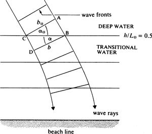
Consider a deep-water wave approaching the transitional depth limit ([math]h/L_0 =0.5[/math]), as shown in Figure 6. A wave travelling from A to B (in deep water) traverses a distance [math]L_0[/math] in one wave period [math]T[/math]. However, the wave travelling from C to D traverses a smaller distance, L, in the same time, as it is in the transitional depth region. Hence, the new wave front is now BD, which has rotated with respect to AC.
Letting the angle [math]\alpha[/math] represent the angle of the wave front to the depth contour, then
[math]\sin \alpha = L/BC[/math] and [math]\sin \alpha_0=L_0/BC[/math]. Hence
[math]\Large\frac{\sin \alpha }{\sin \alpha _{0} }\normalsize =\Large\frac{L}{L_{0} }\normalsize =\Large\frac{c}{c_{0} }\normalsize =\tanh \left(kh\right) . \qquad (4.2) [/math]
As [math]c \lt c_0[/math] then [math]\alpha \lt \alpha_0[/math], which implies that as a wave approaches a shoreline from an oblique angle the wave fronts tend to align themselves with the underwater contours. Figure 7 shows the variation of [math]c/c_0[/math] with [math]h/L_0[/math], and [math]\alpha / \alpha_0[/math] with [math]h/L_0[/math] (the later specifically for the case of parallel contours). It should be noted that [math]L_0[/math] is used in preference to [math]L[/math] as the former is a fixed quantity.
In the case of non-parallel contours, individual wave rays (i.e. the orthogonals to the wave fronts) must be traced. Figure 7 can still be used to find [math]\alpha[/math] at each contour if [math]\alpha_0[/math] is taken as the angle (say [math]\alpha_1[/math]) at one contour and [math]\alpha[/math] is taken as the new angle (say [math]\alpha_2[/math]) to the next contour. The wave ray is usually taken to change direction midway between contours. This procedure may be carried out by hand using tables or figures [10] or by computer as described later in this section.
Equation (4.2) is also known as Snell’s law, according to which [math] \sin \alpha / c[/math] = constant along a wave ray. Multiplication with the radial frequency [math]\omega[/math] shows that similar constancy holds for the component of the wave vector [math]\vec k [/math] parallel to the depth contour (the wave vector [math]\vec k [/math] follows the wave propagation direction and its length equals the wave number [math]k=\omega /c[/math]).
It can be shown that Snell’s law can also be expressed as
[math] \vec \nabla \times \vec k |_{vertical component} \equiv \partial (k \sin \alpha) / \partial x - \partial (k \cos \alpha) / \partial y =0 . \qquad (4.3) [/math]
The proof that this Equation is equivalent to (4.2) is given in Dean & Dalrymple [5].
The wave energy conservation equation reads
[math] \partial (E c_g \cos \alpha) / \partial x + \partial (E c_g \sin \alpha) / \partial y = - \epsilon_d , \qquad (4.4) [/math]
where [math] \epsilon_d[/math] represents energy losses (due to seabed friction, cf Equation (4.4)). Koutitas [11] gives a worked example of a numerical solution to Equations (4.3) and (4.4).
Shoaling
Consider first a wave front travelling parallel to the seabed contours (ie no refraction is taking place). Making the assumption that wave energy is transmitted shorewards without loss due to bed friction or turbulence, then from Equation (8),
[math] \Large\frac{P}{P_{0} }\normalsize =1=\Large\frac{Ec_{g} }{E_{0} c_{g_{0} } }\normalsize. \qquad (4.5)[/math]
Substituting Equation (3.22) gives
[math]\Large\frac{P}{P_{0} }\normalsize =1=\left(\Large\frac{H}{H_{0} }\normalsize \right)^{2} \Large\frac{c_{g} }{c_{g_{0} } }\normalsize ,\quad \Large\frac{H}{H_{0} }\normalsize =\left(\Large\frac{c_{g_{0} } }{c_{g} }\normalsize \right)^{1/ 2}=K_{S} , [/math]
where [math]K_S[/math] is the shoaling coefficient.
The shoaling coefficient can be evaluated from the equation for the group wave celerity, Equation (3.23),
[math]K_S =\left( \Large\frac{c_{g_0} }{c_g}\normalsize \right)^ {1/2}=\left[ (c/c_0 ) ( 1+\Large\frac{2kh}{\sinh 2kh}\normalsize ) \right]^ {-1/2} . \qquad (4.6) [/math]
The variation of [math]K_S[/math] with [math]d/L_0[/math] is shown in Figure 8.
Combined refraction and shoaling
Consider next a wave front travelling obliquely to the seabed contours as shown in Figure 9. In this case, as the wave rays bend, they may converge or diverge as they travel shoreward. At the contour [math]h/L_0 = 0.5, \quad BC=b_0 / \cos \alpha _0 =b / \cos \alpha . [/math] Thus
[math]b/b_0 = \cos \alpha / \cos \alpha _0 . \qquad (4.7)[/math]
Again, assuming that the power transmitted between any two wave rays is constant (i.e. conservation of wave energy flux), then
[math]\Large\frac{P}{P_0}\normalsize = 1 =\Large\frac{E b c_g}{E_0 b_0 c_{g_0 }}\normalsize = \left( \Large\frac{H}{H_0}\normalsize \right)^2 \Large\frac{\cos \alpha }{\cos \alpha _0 }\normalsize \Large\frac{c_g }{c_{g_0 }}\normalsize . \qquad (4.8)[/math]
Hence
[math]H/H_0=K_R K_S , \qquad (4.9) [/math]
where [math]K_{R} =\left( \cos \alpha _{0} /\cos \alpha \right)^{1/2}[/math] is called the refraction coefficient.
For the case of parallel contours, [math]K_R[/math] can be found using Figure 9. In the more general case, [math]K_R[/math] can be found from the refraction diagram directly by measuring [math]b[/math] and [math]b_0[/math].
As the refracted waves enter the shallow water region, they break before reaching the shoreline. The foregoing analysis is not strictly applicable to this region, because the wave fronts steepen and are no longer described by the Airy waveform. However, it is common practice to apply refraction analysis up to the so-called breaker line. This is justified on the grounds that the inherent inaccuracies are small compared with the initial predictions for deep-water waves, and are within acceptable engineering tolerances. To find the breaker line, it is necessary to estimate the wave height as the wave progresses inshore and to compare this with the estimated breaking wave height at any particular depth. As a general guideline, waves will break when
[math] h_{b} =1.28H_{b} , \qquad (4.10)[/math]
where the subscript b refers to the point of breaking. The subject of wave breaking is of considerable interest both theoretically and practically.
Bathymetry effects on Refraction
In general, the seabed contours are not straight and parallel, but are curved. This results in some significant refraction effects. Within a bay, refraction will generally spread the wave rays over a larger region, resulting in a reduction of the wave heights. Conversely, at headlands the wave rays will converge, resulting in larger wave heights. Over offshore shoals the waves may be focused, resulting in a small region where the wave heights are much larger. If the focusing is so strong that the wave rays are predicted to cross, then the wave heights become so large as to induce wave breaking.
Shoaling and refraction of directional wave spectra
So far, the discussion of shoaling and refraction has been restricted to considering waves of single period, height and direction ( a monochromatic wave ). However, a real sea state is more realistically represented as being composed of a large number of components of differing periods, heights and directions (known as the directional spectrum). Therefore, in determining an inshore sea state due account should be taken of the offshore directional spectrum.
This can be achieved in a relatively straightforward way, provided the principle of linear superposition can be applied. This implies that non-linear processes such as seabed friction and higher-order wave theories are excluded. The principle of the method is to carry out a refraction and shoaling analysis for every individual component wave frequency and direction and then to sum the resultant inshore energies at the new inshore directions at each frequency and hence assemble an inshore directional spectrum.
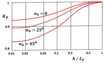
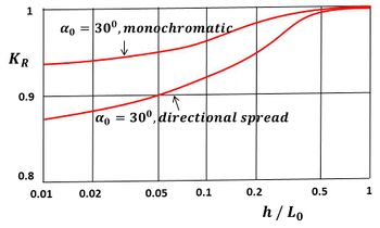
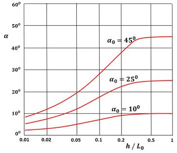
Goda [2] presents a set of design charts for the effective refraction coefficient ([math]K_R [/math]) and predominant wave direction ([math]\alpha_0 [/math]) over parallel contours for a range of relative depths using the Betchneider-Mitsuyasu frequency spectrum and Mitsuyasu spreading function, which facilitate the ready application of the method described above. Figure 10 illustrates some of Goda’s results for [math]K_R [/math] as a function of relative depth for a typical wind wave state. Figure 11 shows a comparison of results for [math]K_R [/math] between a monochromatic wave and Goda’s result for a directional spectrum of a typical wind wave state. Figure 12 shows some of Goda’s results for the principal wave direction at a range of relative depths for a typical wind wave state.
Seabed Friction
In the foregoing analysis of refraction and shoaling it was assumed that there was no loss of energy as the waves were transmitted inshore. In reality, waves in transitional and shallow water depths will be attenuated by wave energy dissipation through seabed friction. Such energy losses can be estimated, using linear wave theory, in an analogous way to pipe and open channel flow frictional relationships. In contrast to the velocity profile in a steady current, the frictional effects under wave action produce an oscillatory wave boundary layer which is very small (a few millimetres or centimetres). In consequence, the velocity gradient is much larger than in an equivalent uniform current that in turn implies that the wave friction factor will be many times larger.
Firstly, the mean seabed shear stress ([math]\tau_b[/math] ) may be found using
[math]\tau _{b} =\Large\frac{1}{2}\normalsize f_{w} \rho u_{m}^{2} , \qquad (4.11) [/math]
where [math]f_w[/math] is the wave friction factor and [math]u_m[/math] is the maximum near bed orbital velocity; [math]f_w[/math] is a function of a local Reynolds' number ([math]Re_w[/math]) defined in terms of [math]u_m[/math] (for velocity) and either [math]a_b[/math], wave amplitude at the bed or the seabed grain size [math]k_s[/math] (for the characteristic length). A diagram relating [math]f_w[/math] to [math]Re_w[/math] for various ratios of [math]a_b/k_s[/math], due to Jonsson, is given in Dyer [12]. This diagram is analogous to the Moody diagram for pipe friction factor ([math]\lambda[/math]). Values of [math]f_w[/math] may take values in the range [math]\; 0.5 \times 10^{-3} - 5 \;[/math]. Hardisty[13] summarizes field measurements of [math]f_w[/math] (from Sleath) and notes that a typical field value is about 0.1. Soulsby [14] provides details of several equations which may be used to calculate the wave friction factor. For rough turbulent flow in the wave boundary layer, he derived a new formula which best fitted the available data, given by
[math]f_w=0.237 r^{-0.52}, \quad r=A/k_s, \quad A=u_m T/2 \pi . \qquad (4.12) [/math]
Using linear wave theory [math]u_m[/math] is given by [math]u_{m} =\pi H / (T\sinh kh) .[/math]
The rate of energy dissipation may then be found by combining the expression for [math]\tau_b[/math] with linear wave theory to obtain
[math]\Large\frac{dH}{dx}\normalsize =-\Large\frac{4f_{w} k^{2} H^{2} }{3\pi \sinh (kh)(\sinh (2kh)+2kh)}\normalsize . \qquad (4.13) [/math]
The wave height attenuation due to seabed friction is of course a function of the distance travelled by the wave as well as the depth, wavelength and wave height. Thus the total loss of wave height ([math]\Delta H_f[/math]) due to friction may be found by integrating over the path of the wave ray.
BS6349 [15] presents a chart from which a wave height reduction factor may be obtained. Except for large waves in shallow water, seabed friction is of relatively little significance. Hence, for the design of maritime structures in depths of 10 m or more, seabed friction is often ignored. However, in determining the wave climate along the shore, seabed friction is now normally included in numerical models, although an appropriate value for the wave friction factor remains uncertain and is subject to change with wave induced bed forms. Furthermore, wave energy losses due to other physical processes such as breaking can be more significant.
Wave-Current Interaction
So far, consideration of wave properties has been limited to the case of waves generated and travelling on quiescent water. In general, however, ocean waves are normally travelling on currents generated by tides and other means. These currents will also, in general, vary in both space and time. Hence two distinct cases need to be considered here. The first is that of waves travelling on a current and the second when waves generated in quiescent water encounter a current (or travel over a varying current field).
For waves travelling on a current, two frames of reference need to be considered. The first is a moving or relative frame of reference, travelling at the current speed. In this frame of reference, all the wave equations derived so far still apply. The second frame of reference is the stationary or absolute frame. The concept which provides the key to understanding this situation is that the wavelength is the same in both frames of reference. This is because the wavelength in the relative frame is determined by the dispersion equation and this wave is simply moved at a different speed in the absolute frame. In consequence, the absolute and relative wave periods are different.
Consider the case of a current with magnitude ([math]u[/math]) following a wave with wave celerity ([math]c[/math]), the wave speed with respect to the seabed ([math]c_a[/math]) becomes [math]c + u[/math]. As the wavelength is the same in both reference frames, the absolute wave period will be less than the relative wave period. Consequently, if waves on a current are measured at a fixed location (eg in the absolute frame), then it is the absolute period ([math]T_a[/math]) which is measured. The current magnitude must, therefore, also be known in order to determine the wavelength. From the dispersion Equation (3.12) it follows that
[math]c_a=L/T_a=\left(\Large\frac{gL}{2\pi }\normalsize \tanh \Large\frac{2\pi h}{L}\normalsize \right)^ {1/2} +u . \qquad (4.14)[/math]
This equation thus provides an implicit solution for the wavelength in the presence of a current when the absolute wave period has been measured.
Conversely, when waves travelling in quiescent water encounter a current, changes in wave height and wavelength will occur. This is because as waves travel from one region to the other requires that the absolute wave period remains constant for waves to be conserved. Consider the case of an opposing current, the wave speed relative to the seabed is reduced and therefore the wavelength will also decrease. Thus wave height and steepness will increase. In the limit the waves will break when they reach limiting steepness. In addition, as wave energy is transmitted at the group wave speed, waves cannot penetrate a current whose magnitude equals or exceeds the group wave speed and thus wave breaking and diffraction will occur under these circumstances. Such conditions can occur in the entrance channels to estuaries when strong ebb tides are running, creating a region of high, steep and breaking waves.
Another example of wave-current interaction is that of current refraction. This occurs when a wave obliquely crosses from a region of still water to a region in which a current exits or in a changing current field. The simplest case is illustrated in Figure 13 showing deep-water wave refraction by a current.
In an analogous manner to refraction caused by depth changes, Jonsson showed that in the case of current refraction
[math]\sin \alpha _{c} =\Large\frac{\sin \alpha }{\left(1-\frac{u}{c} \sin \alpha \right)^{2} }\normalsize . \qquad (4.15) [/math]
The wave height is also affected and will decrease if the wave orthogonals diverge (as shown) or increase if the wave orthogonals converge. For further details of wave-current interactions, the reader is referred to Hedges [16] in the first instance.
Wave Reflection
Waves normally incident on solid vertical boundaries (e.g. harbour walls and sea walls) are reflected such that the reflected wave has the same phase but opposite direction and substantially the same amplitude as the incident wave. This fulfils the necessary boundary condition that the horizontal velocity is always zero. The resulting wave pattern set up is called a standing wave, as shown in Figure 14. Reflection can also occur when waves enter a harbour or estuary. This can lead to `resonance' where the waves are amplified.
The equation of the standing wave (subscript s) may be found by adding the two waveforms of the incident (subscript i) and reflected (subscript r) waves. Thus,
[math]\eta _{s} =\eta _{i} +\eta _{r} , \qquad \eta _{i} =\Large\frac{H_{i} }{2}\normalsize \cos \left\{2\pi \left(\Large\frac{x}{L}\normalsize -\Large\frac{t}{T}\normalsize \right)\right\}, \qquad \eta _{r} =\Large\frac{H_{r} }{2}\normalsize \cos \left\{2\pi \left(\Large\frac{x}{L}\normalsize +\Large\frac{t}{T}\normalsize \right)\right\} , \qquad (4.16) [/math]
Taking [math]H_r=H_i =H_s / 2[/math], then
[math] \eta_s=H_s \cos (2 \pi x/L) \cos (2 \pi t/T) . \qquad (4.17) [/math]
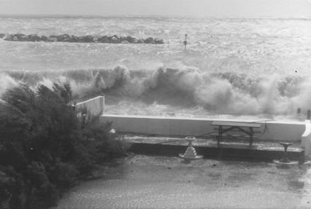
At the nodal points there is no vertical movement with time. By contrast, at the antinodes, crests and troughs appear alternately. For the case of large waves in shallow water and if the reflected wave has a similar amplitude to the incident wave, then the advancing and receding crests collide in a spectacular manner, forming a plume known as a clapotis (see Figure 15). This is commonly observed at sea walls. Standing waves can cause considerable damage to maritime structures, and bring about substantial erosion.
Clapotis Gaufre
When the incident wave is at an angle [math]\alpha[/math] to the normal from a vertical boundary, then the reflected wave will be in a direction [math]\alpha[/math] on the opposite side of the normal. This is illustrated in Figures 16 and 17. The resulting wave motion (the clapotis gaufre) is complex, but essentially consists of a diamond pattern of island crests which move parallel to the boundary. It is sometimes referred to as a short crested system. The crests form at the intersection of the incident and reflected wave fronts. The resulting particle displacements are also complex, but include the generation of a pattern of moving vortices. A detailed description of these motions may be found in Silvester [10]. The consequences of this in terms of sediment transport may be severe. Very substantial erosion and longshore transport may take place. Considering that oblique wave attack to sea walls is the norm rather than the exception, the existence of the clapotis gaufre has a profound influence on the long term stability and effectiveness of coastal defence works. This does not seem to have been fully understood in traditional designs of sea walls, with the result that collapsed sea walls and eroded coastlines have occurred.
Mach Stem
When periodic or solitary waves approach a steep barrier at an oblique angle, the amplitude of the wave against the barrier may be magnified by a phenomenon known as the Mach Stem. The crest immediately adjacent to the wall alters its alignment to create a wave travelling along the face of the wall with increased crest height and this is the Mach Stem wave, illustrated in Figure 17. This reflection phenomenon was first discovered in aerodynamics, but is equally applicable to water waves for which it can begin to occur when the angle of obliquity to the wall becomes less than about 45 degrees. The height of the crest gives rise to a velocity that is equivalent to the component of the incident wave's celerity in the direction of the alignment of the wall. Since the waves do not strike the wall due to a growing slipstream zone, reflection is much reduced until for angles of obliquity less than about 20 degrees reflection becomes non-existent.
Miles [17] demonstrated theoretically that the Mach Stem wave could be amplified by as much as four times the incoming waves, two time greater than a linear superposition of incident and reflected wave. However, Melville [18] was unable to reproduce such large amplification factors in the laboratory. More recently Yoon and Liu [19] employed parabolic approximations to study the stem waves induced by an oblique cnoidal wave train in front of a vertical barrier and Honda and Mase [20] have applies a non-linear frequency-domain wave model to mach stem evolution and wave transformation on a reef structure.
In practical design terms it is important to recognise the potential for Mach stem waves to exist as the enhanced wave height and high velocities running along a breakwater can result in increased overtopping, armour instability, toe scour problems and beach erosion at the root.
Wave reflection coefficients
Defining a reflection coefficient [math]K_r = H_r /H_i[/math] then typical values are as follows
| Reflection barrier | [math]K_r[/math] |
|---|---|
| Concrete sea walls | 0.7 to 1.0 |
| Rock breakwaters | 0.4 to 0.7 |
| Beaches | 0.05 to 0.2 |
It should be noted that the reflected wave energy is equal to [math]K_r^2[/math] as energy is proportional to [math]H^2[/math].
Predictive Equations for Wave Reflection from Rock Slopes
The Rock Manual[21]) gives an excellent summary of the development of wave reflection equations based on laboratory data of reflection from rock breakwaters. This work clearly demonstrates that rock slopes considerably reduce reflection compared to smooth impermeable slopes. Based on this data, the best fit equation was found to be
[math]K_{r} =0.125\xi _{p}^{0.7} , \qquad (4.18)[/math]
where [math]\xi _{p} [/math] is the Iribarren Number = [math]\tan \beta (H/L_p)^{-1/2} [/math] and the subscript [math]p[/math] refers to peak frequency.
Davidson et al [22] subsequently carried out an extensive field measurement programme of wave reflection at prototype scale at the Elmer breakwaters (Sussex, UK) and after subsequent analysis proposed a new predictive scheme. A new dimensionless reflection parameter was proposed given by
[math] R=\Large\frac{d_{t} L_0^{2} }{H_{i} D^{2} \cot \beta }\normalsize , \qquad (4.19)[/math]
where [math]d_t[/math] (m) is water depth at the toe of structure, [math]L_0[/math] is deep water wavelength at peak frequency, [math]H_i[/math] is significant incident wave height, [math]D[/math] is characteristic diameter of rock armour and [math]\tan \beta[/math] is the structure gradient. [math]R[/math] was found to be a better parameter than [math]\xi[/math] in predicting wave reflection. The reflection coefficient is then given by
[math] K_r = 0.151 R^{0.11} \qquad (4.20) [/math]
or, alternatively
[math] K_{r} =\Large\frac{0.635 R^{0.5} }{41.2+R^{0.5} }\normalsize . \qquad (4.21)[/math]
Wave reflection due to refraction
Wave reflection due to refraction alone can also occur due to very rapid changes in the seabed. In particular, when waves approach a deep dredged channel with the direction or propagation at a sufficiently acute angle to the dredged side slope and there is a sufficiently large change in water depth which, in turn, results in a large and rapid change in wave speed, the wave may reflect off the side of the channel. An analogous example of this phenomenon is the internal reflection of light rays in a glass prism due to changes in wave speed between the glass (shallow water) and air (deep water), the essential difference being that, as wave speed is a function of water depth, it is not a constant on the wave approach or on the channel side slope. This is a very real phenomenon and, if not recognised, can result in wave energy inadvertently being reflected into a port area. The converse also applies as this process can also be used to advantage to reflect wave energy away from a harbour entrance. It should also be appreciated that longer period waves will also be more susceptible to this phenomenon due to the their relatively greater speed in deeper water. When it comes to wave modelling described in Section 3.9 it follows that any numerical grid used in a wave model must be fine enough to capture the detail of the dredged channel in order to properly reproduce this effect.
Wave Diffraction
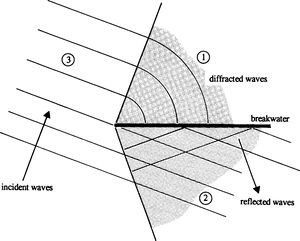
This is the process whereby waves bend round obstructions by radiation of the wave energy. Figure 18 shows an oblique wave train incident on the tip of a breakwater. There are three distinct regions:
- the shadow region in which diffraction takes place;
- the short crested region in which incident and reflected waves form a clapotis gaufre;
- an undisturbed region of incident waves.
In region (1) the waves diffract with the wave fronts forming circular arcs centred on the point of the breakwater. When the waves diffract, the wave heights diminish as the energy of the incident wave spreads over the region. The real situation is, however, more complicated than that presented in Figure 18. The reflected waves in region (2) will diffract into region (3) and hence extend the short crested system into region (3).
Mathematical Formulation of Wave Diffraction
Mathematical solutions for wave diffraction have been developed for the case of constant water depth using linear wave theory. The basic differential equation for wave diffraction is known as the Helmholtz equation. This can be derived from the Laplace equation (refer to “Section Small amplitude wave theory” Equation (3.7)) in three dimensions
[math]\Large\frac{\partial^2 \phi}{\partial x^2}\normalsize+\Large\frac{\partial^2 \phi}{\partial y^2}\normalsize+\Large\frac{\partial^2 \phi}{\partial z^2}\normalsize = 0 . \qquad (4.22)[/math]
Now, let
[math]\phi(x,y,z) = Z(z) F(x,y) e^{i \omega t}[/math],
(i.e. [math]\phi[/math] is a function of depth and horizontal co-ordinates and is periodic and [math]i[/math] is the imaginary number ). For uniform depth an expression for [math]Z(z)[/math] satisfying the no flow bottom boundary condition is [math]Z(z)=\cosh (k(h+z))[/math].
Substituting for [math]\phi[/math] and [math]Z[/math] in the Laplace equation leads (after further manipulation) to the Helmholtz equation
[math]\Large\frac{\partial^2 F}{\partial x^2}\normalsize+\Large\frac{\partial^2 F}{\partial y^2}\normalsize+k^2 F(x,y)=0 . \qquad (4.23)[/math]
Solutions to the Helmholtz Equation
A solution to the Helmholtz equation was first found by Sommerfeld in 1896 who applied it to the diffraction of light (details may be found in Dean & Dalrymple (1991)). Somewhat later, Penney & Price (1952) showed that the same solution applied to water waves and presented solutions for incident waves from different directions passing a semi-infinite barrier and for normally incident waves passing through a barrier gap [math]b[/math]. For the case of normal incidence on a semi-infinite barrier, it may be noted that, for a monochromatic wave, the diffraction coefficient [math]K_d[/math] (ratio of incident and diffracted wave height) is approximately 0.5 at the edge of the shadow region and that [math]K_d[/math] exceeds 1.0 in the 'undisturbed' region due to diffraction of the reflected waves caused by the (perfectly) reflecting barrier. Their solution for the case of a barrier gap is essentially the superposition of the results from two mirror image semi-infinite barriers.
Their diagrams apply for a range of gap width to wavelength ([math]b/L[/math]) from 1 to 5. When [math]b/L[/math] exceeds 5 the diffraction patterns from each barrier do not overlap and hence the semi-infinite barrier solution applies. For [math]b/L[/math] less than one the gap acts as a point source and wave energy is radiated as if it were coming from a single point at the centre of the gap. It is important to note here that these diagrams should not be used for design. This is because of the importance of considering directional wave spectra.
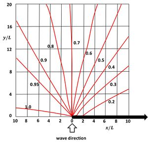
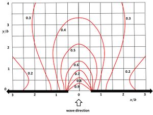
Goda (2000) pioneered the use of wave directional spectra in the determination of wave diffraction. In a similar manner to the technique described in the section on refraction and shoaling of directional spectra, he calculated an effective diffraction coefficient from the superposition of diffraction of all the component wave directions and frequencies present in a typical wind wave state and hence constructed a new set of diffraction diagrams.
These diagrams show that the diffraction of a directional random sea state differs quite markedly from the case of a monochromatic sea. At the edge of the shadow zone for a semi-infinite barrier [math]K_d[/math] is approximately 0.7 (cf. [math]K_d[/math]= 0.5 for a monochromatic wave), and waves of greater height penetrate the shadow zone at equivalent points. This is illustrated in Figure 19. For the case of a barrier gap (width [math]b[/math]), the wave height variations are smoothed compared with the monochromatic case, with smaller heights in the area of direct penetration and larger heights in the shadow regions, as shown in Figure 20.
Combined refraction and diffraction
Refraction and diffraction often occur together. For example, the use of a wave ray model over irregular bathymetry may produce a caustic (i.e. a region where wave rays cross). Here diffraction will occur spreading wave energy away from regions of large wave heights. Another example is around offshore breakwaters; here diffraction is often predominant close to the structure with refraction becoming more important further away from the structure. A solution to the Laplace equation over irregular bathymetry is required, which allows diffraction as well as refraction. Such a solution was first derived in 1972 by Berkhoff[23]. This is generally known as the mild slope equation because the solution is restricted to slowly bathymetry that varies slowly relative to the wavelength. It may be written as
[math] \Large\frac{\partial }{\partial x}\normalsize \left(cC_{g} \Large\frac{\partial \phi }{\partial x}\normalsize \right)+\Large\frac{\partial }{\partial y}\normalsize \left(cC_{g} \Large\frac{\partial \phi }{\partial y}\normalsize \right)+\omega ^{2} \Large\frac{C_{g} }{c}\normalsize \phi =0 , \qquad (4.24) [/math]
where [math]\phi (x,y)[/math] is a complex wave potential function. The solution of this equation is highly complex and beyond the scope of this text. However, the interested reader is directed to Dingemans [24] for a review of the subject. One of the more recent developments in solving the mild slope equation is that due to Li [25]. This version of the mild slope equation allows the simultaneous solution of refraction, diffraction and reflection.
It has also been the subject of a field validation study. Initial results may be found in Ilic and Chadwick [26]. They tested this model at the site of the Elmer offshore breakwater scheme (shown in Figure 21) where refraction and reflection are the main processes seaward of the breakwaters with diffraction and refraction taking place shoreward of the breakwaters, and in a physical model (shown in Figure 22). Figure 23 illustrates wave diffraction at the Happisburgh to Winterton scheme, Norfolk, England.
Finite amplitude waves
It has already been noted that the Airy wave equations only strictly apply to waves of relatively small height in comparison to their wavelength and water depth. For steep waves and shallow water waves the profile becomes asymmetric with high crests and shallow troughs. For such waves, celerity and wavelength are affected by wave height and are better described by other wave theories. To categorise finite amplitude waves, three parameters are required. These are the wave height ([math]H[/math]), the water depth ([math]h[/math]) and wavelength ([math]L[/math]). Using these parameters various non-dimensional parameters can be defined, namely relative depth ([math]h/L[/math]), wave steepness ([math]H/L[/math]) and wave height to water depth ratio ([math]H/h[/math]). Another useful non-dimensional parameter, first introduced in 1953, is the Ursell number
[math]U_r= \Large\frac{H L^{2}}{h^{3}}\normalsize . \qquad (5.1)[/math]
The first finite amplitude wave theory was developed by Stokes in 1847. It is applicable to steep waves in deep and transitional water depths. Following Stokes, Korteweg and de Vries developed a shallow water finite amplitude wave theory in 1895. They termed this Cnoidal theory, analogous to the sinusiodal Airy wave theory. Both of these theories relax the assumptions made in Airy theory which, as previously described, linearises the kinematic and dynamic surface boundary conditions. In Stokes' wave theory [math]H/L[/math] is assumed small and [math]h/L[/math] is allowed to assume a wide range of values. The kinematic free surface boundary condition is then expressed as a power series in terms of [math]H/L[/math], and solutions up to and including the nth order of this power series are sought. Stokes derived the second order solution. In Cnoidal theory, [math]H/h[/math] is assumed small and [math]U_r[/math] of the order of unity. Korteweg and de Vries derived a first order solution. Much more recently (1960's to 1980's), these two theories have been extended to higher orders (third and fifth). The mathematics is complex and subsequently other researchers developed new methods whereby solutions could be obtained to any arbitrary order, by numerical solution.
Stokes' solution for the surface profile is given by:
[math]\eta =\Large\frac{H}{2}\normalsize \cos \left\{2\pi \left(\Large\frac{x}{L}\normalsize -\Large\frac{t}{T}\normalsize \right)\right\}+\Large\frac{\pi H}{8}\normalsize \left(\Large\frac{H}{L}\normalsize \right)\Large\frac{\cosh(kh)(2+\cosh(2kh))}{\sinh ^{3} kh}\normalsize \cos \left\{4\pi \left(\Large\frac{x}{L}\normalsize -\Large\frac{t}{T}\normalsize \right)\right\} . \qquad (5.2)[/math]
This equation differs from the linear solution by the addition of the second order term. Its frequency is twice that of the first order term, which therefore increases the crest height, decreases the trough depth and thus increases the wave steepness. To second order, the wave celerity remains the same as linear theory. However, to third order the wave celerity increases with wave steepness and is approximately 20% higher than given by linear theory in deep water at the limiting steepness (1/7).
A full mathematical description of all these theories is beyond the scope of this book and the reader is referred to Dean and Dalrymple [5] and Sorensen [4] for further details. However, it is useful here to provide some information on the circumstances under which these finite amplitude wave theories can be applied. Figure 24, taken from Hedges [27], provides useful guidance. It may be noted that the range of validity of linear theory is reassuringly wide, covering all of the transitional water depths for most wave steepnesses encountered in practice. For engineering design purposes, the main implication of using linear theory outside its range of validity is that wave celerity and wavelength are not strictly correct, leading to (some) inaccuracies in refraction and shoaling analysis. In addition, the presence of asymmetrical wave forms will produce harmonics in the Fourier analysis of recorded wave traces which could be incorrectly interpreted as free waves of higher frequency.
Wave forces
Wave forces on coastal structures are highly variable and depend on both the wave conditions and the type of structure being considered. Three cases of wave conditions need to be considered, comprising unbroken, breaking and broken waves. Coastal structures may also be considered as belonging to one of three types, vertical walls (e.g. sea walls, caisson breakwaters), rubble mound structures (e.g. rock breakwaters, concrete armoured breakwaters) and individual piles (e.g. for jetty construction). Here consideration is limited to outlining some of the concepts and mentioning some of the design equations that have been developed. More extensive treatments on the design and stability of coastal structures under the influence of waves and currents can be found in the Rock Manual [21] and the Coastal Engineering Manual [28]
Vertical Walls
The forces exerted on a vertical wall by wave action can be considered to be composed of three parts: the static pressure forces, the dynamic pressure forces and the impulsive forces. When the structure is placed such that the incident waves are unbroken, then a standing wave will exist seaward of the wall and only the static and dynamic forces will exist. These can be readily determined from linear wave theory. As a standing wave comprises two superposed progressive waves, travelling in opposite directions, the resulting equation for pressure under a standing wave is of the same form as that for a progressive wave. The standing wave height must be used in the equation, rather than the incident wave height. However, more commonly the structure will need to resist the forces produced by breaking or broken waves. The most widely used formulae for estimating the quasi static pulsating forces for either broken or unbroken waves is due to Goda [29][2].
Additionally, very high localised impulsive forces may also arise due to breaking waves. These trap pockets of air, which are rapidly compressed, resulting in highly variable impulse forces (between 10 to 50 times higher than the pulsating forces). The study of this phenomenon is an ongoing area of research and currently there are no widely accepted formulae for the prediction of such forces (see Cuomo et al [30] for recent results). Impact pressure forces are of very short duration (of the order of tenths of a second) and consequently typically affect the dynamic response of the structure rather than its static equilibrium. See also Wave collision on a vertical wall.
Rubble Mound
In the case of rubble mound structures, the waves will generally break on the structure and their energy is partly dissipated by turbulence and friction, with the remaining energy being reflected and possibly transmitted. Many breakwaters are constructed using large blocks of rock (the 'armour units') placed randomly over suitable filter layers. More recently, rock has been replaced by numerous shapes of massive concrete blocks (for example, dolos, tetrapod and cob). The necessary size of the armour units depends on several interrelated factors (wave height, amour unit type and density, structure slope and permeability). Traditionally, the Hudson formula has been used. This was derived from an analysis of a comprehensive series of physical model tests on breakwaters with relatively permeable cores and using regular waves. More recently (1985-1993) these formulas have been superseded by formulas developed from an extensive series of physical model tests. In these tests random waves were used and the influence of wave period and number of storm waves were also considered. A new damage criterion and a notional core permeability factor were developed. The equations are for use where the structure is placed in deep water with the waves either breaking on the structure or causing surging. See for further details Stability of rubble mound breakwaters and shore revetments and the Rock Manual[21].
Vertical Piles
Finally for the case of unbroken wave forces on piles, the Morrison equation [31] is an option that is used for design. This equation presumes that there are two forces acting. These are a drag force ([math]F_D[/math]) induced by flow separation around the pile and an inertia force ([math]F_I[/math]) due to the flow acceleration. For the case of a vertical pile, only the horizontal velocities ([math]u[/math]) and accelerations ([math]a_x[/math]) need be considered (see Equations 4b, 4c). The drag and inertia forces per unit length of pile of diameter [math]D[/math] are given by
[math]F_D=C_D \rho D u|u| [/math], where [math]C_D[/math] is a drag coefficient, and
[math] F_I= \rho C_M (\pi D^2 / 4) a_x [/math], where [math]C_M[/math] is an inertia coefficient.
The total ‘in-line’ foce is given by [math]F=F_D+F_I . \qquad (6.1)[/math]
Morrison's equation is derived from a combination of theoretical considerations and empirical evidence, not from first principles. The equation does not include lift and slam forces and is most appropriately applied to slender circular piles or pipes subject to unbroken waves. Considering linear waves the velocity [math]u[/math] and corresponding component of acceleration are given by Equation 4b and 4c respectively. The result is
[math]F=\Large\frac{C_D \rho D A^2 \omega^2}{8}\normalsize \cos(kx- \omega t) |\cos(kx- \omega t)| + \Large\frac{C_M \rho \pi D^2 A \omega^2}{8}\normalsize \sin (kx - \omega t) . \qquad (6.2)[/math]
Both these forces reduce with increasing depth and are 90[math]^{\circ}[/math] out of phase. The total force acting on a vertical pile must be found as their sum, integrated over the length of the pile. Typical values of [math]C_D[/math] and [math]C_M[/math] for cylinders are 1 and 2 respectively. The number A/D has special significance and is known as the Keulegan-Carpenter number. Accurate values of [math]C_D[/math] and [math]C_M[/math] are difficult to establish from field measurements, but recommended values have been published (see the Coastal Engineering Manual [28]and BS6349 [15]). Both numbers are functions of Reynolds' number [math]Re[/math] and Keulegan-Carpenter number. Results from many laboratory and field experiments have been compiled by the US Army Coastal Engineering Centre who have recommended design values for shown in the tables below.
| Reynolds number | [math]C_M[/math] |
|---|---|
| [math]Re \lt 2.5 \times 10^5[/math] | [math]2.0[/math] |
| [math]2.5 \times 10^5 \lt Re \lt 5 \times 10^5 [/math] | [math]2.5 - 2 \times 10^{-6} Re[/math] |
| [math]Re \gt 5 \times 10^5[/math] | [math]1.5[/math] |
| Reynolds number | [math]C_D[/math] |
|---|---|
| [math]Re \lt 10^5[/math] | [math]1.2[/math] |
| [math] 10^5 \lt Re \lt 4 \times 10^5 [/math] | [math]0.6 - 1.2[/math] |
| [math]Re \gt 4 \times 10^5[/math] | [math]0.6 - 0.7[/math] |
If these tables are used then the Reynolds number must be calculated using the maximum velocity associated with the wave.
Surf Zone Processes
A General Description of the Surf Zone
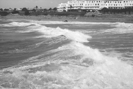
For simplicity, consider the case of a coast with the seabed and beach consisting of sand. The bed slope will usually be fairly shallow (say 0.01 [math] \lt \beta \lt [/math] 0.03). Waves will therefore tend to start to break at some distance offshore of the beach or shoreline (i.e. the beach contour line which corresponds to the Still Water Level, see Figure 25). At this initial break point the wave will be of height [math]H_b[/math] and at angle [math]\alpha_b[/math] to the beach line. The region between this initial point and the beach is known as the surf zone. In this region, the height of an individual wave is largely controlled by the water depth. The wave height will progressively attenuate as it advances towards the beach, and the characteristic foam or surf formation will be visible on the wave front (see Figure 26 for a real example).
The mechanics of this progressive breaking are very complex. A brief summary is as follows:
- Turbulence and aeration are produced.
- Significant rates of change are induced in the momentum of the elements of fluid which constitute the wave. This produces a momentum force which may be resolved into two components (Figure 25). The component which lies parallel to the shoreline is the cause of a corresponding 'longshore current'. The component which is perpendicular to the shoreline produces an increase in the depth of water above the Still Water Level, and this is usually called the 'set up'.
- Energy is lost due to bed friction and due to the production of turbulence. The frictional losses are produced both by the oscillatory motion at the seabed due to the wave and by the unidirectional motion of the longshore current. The two motions are not completely independent, and their interaction has significant effects on the bed friction.
Wave Breaking
There are two criteria which determine when a wave will break. The first is a limit to wave steepness and the second is a limit on the wave height to water depth ratio. Theoretical limits have been derived from solitary wave theory, which is a single wave with a crest and no trough. Such a wave was first observed by Russell in 1840, being produced by a barge on the Forth and Clyde canal. The two criteria are given by:
- Steepness [math]H/L \lt 1/7[/math]. This normally limits the height of deep water waves.
- Ratio of height to depth: the breaking index [math]\gamma = H/h = 0.78[/math].
In practice [math]\gamma[/math] can vary from about 0.4 to 1.2 depending on beach slope and breaker type.
Goda [2] provides a design diagram for the limiting breaker height of regular waves, which is based on a compilation of a number of laboratory results. He also presents an equation, which is an approximation to the design diagram, given by:
[math]\Large\frac{H_{b} }{L_{o} }\normalsize =0.17\left\{1-\exp \left[-\Large\frac{1.5\pi h}{L_{o} }\normalsize \left(1+15\tan ^{4/3} \beta \right)\right]\right\}. \qquad (7.1)[/math]
where [math]\tan \beta[/math] is the beach slope, [math]H_b[/math] the wave height at breaking and [math]L_0[/math] the deep-water wavelength. For the case of random Goda [2] also presents an equation set to predict the wave heights within the surf zone, based on a compilation of field, laboratory and theoretical results.
Breaker Types
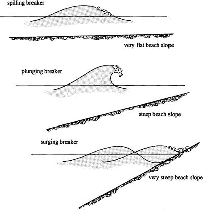
Breaking waves may be classified as one of three types as shown in Figure 27. The type can be approximately determined by the value of the surf similarity parameter (or Iribarren Number) [math]\xi _{b} =\tan \beta /\sqrt{H_{b} /L_{b} }, [/math] where [math]L_b[/math] is the wavelength at breaking.
Spilling breakers (Figure 28) occur when [math] \xi _{b} \lt [/math]0.4, plunging breakers (Figure 29) when 0.4[math]\le \xi _{b} \le [/math]2.0 and surging breakers when [math]\xi _{b} \gt [/math]2.0.
Battjes [32] found from real data that for 0.05 [math] \lt \xi_0 \lt [/math]2 (subscript [math]o[/math] indicates deep water)
[math]\gamma \approx \xi _{0}^{0.17} +0.08 . \qquad (7.2)[/math]
Further details may be found in Horikawa [8] and Fredsoe and Deigaard [33]; see also Breaker index.
Wave set-down and set-up
In the case of shore-perpendicular wave incidence, the onshore momentum flux (i.e. radiation stress) [math]S_{XX}[/math] , defined in Section Radiation Stress Theory, must be balanced by an equal and opposite force for equilibrium. This manifests itself as a slope in the mean still water level (given by [math]d \eta / dx[/math]).
Consider the control volume shown in Figure 30 in which a set up [math]\overline{\eta }[/math] on the still water level exists induced by wave action. The forces acting are the pressure forces [math]F_p[/math], the reaction force on the bottom [math]R_x[/math] and the radiation stresses (all forces are wave period averaged, see section #Radiation Stress (Momentum Flux) and Equation (3.26)). For equilibrium the net force in the [math]x[/math]-direction is zero. Hence
[math](F_{p_{1} } -F_{p_{2} } )+(S_{XX_{1} } -S_{XX_{2} } )-R_{x} =0 , \qquad (7.3)[/math]
where [math]F_{p_{2} } =F_{p_{1} } +\Large\frac{dF_{p} }{dx}\normalsize \delta x , \qquad S_{XX_{2} } =S_{XX_{1} } +\Large\frac{dS_{XX} }{dx}\normalsize \delta x .[/math]
As [math]F_{p} =\Large\frac{1}{2}\normalsize \rho g(h+\overline{\eta })^{2} [/math] (i.e. the hydrostatic pressure force), then
[math]\Large\frac{dF_{p} }{dx}\normalsize =\Large\frac{1}{2}\normalsize \rho g\Large\frac{d}{dx}\normalsize (h+\overline{\eta })^{2} =\rho g(h+\overline{\eta })\left(\Large\frac{dh}{dx}\normalsize +\Large\frac{d\overline{\eta }}{dx}\normalsize \right) \qquad (7.4) [/math]
and as [math]R_x[/math] for a mildly sloping bottom is due to bottom pressure,
[math]R_{x} =\overline{p}\delta h=\overline{p}\Large\frac{dh}{dx}\normalsize \delta x=\rho g(h+\overline{\eta })\Large\frac{dh}{dx}\normalsize \delta x . \qquad (7.5)[/math]
After substitution of Equations (7.4, 7.5) into Equation (7.3) the final result is
[math] \Large\frac{dS_{XX} }{dx}\normalsize +\rho g(h+\overline{\eta })\Large\frac{d\overline{\eta }}{dx}\normalsize =0 , \qquad (7.6)[/math]
where [math]\overline{\eta}[/math] is the difference between the still water level and the mean water level in the presence of waves.
Outside the breaker zone Equation (7.6) may be integrated to obtain
[math] \overline{\eta _{d} }=-\Large\frac{1}{8}\normalsize \Large\frac{kH_{b}^{2} }{\sinh (2kh)}\normalsize . \qquad (7.7) [/math]
This is referred to as the set-down ([math]\overline{\eta _{d} }[/math]) and demonstrates that the mean water level decreases in shallower water. Inside the breaker zone the momentum flux rapidly reduces as the wave height decreases. This causes a set-up ([math]\overline{\eta _{u}} [/math]) of the mean still water level. Making the assumption that inside the surf zone the broken wave height is controlled by depth such that
[math]H=\gamma (\overline{\eta }+h) , \qquad (7.8) [/math]
where [math]\gamma \approx [/math]0.8 , then combining Equations (3.30, 7.6) and (7.8) leads to the result
[math]\Large\frac{d\overline{\eta }}{dx}\normalsize =\Large\frac{1}{1+\Large\frac{8}{3\gamma ^2 } }\normalsize \tan \beta , \qquad (7.9) [/math]
Thus for a uniform beach slope it may be shown that
[math] \overline{\eta _{u} }=\Large\frac{3 \gamma^2}{8}\normalsize (h_{b} -h)+\overline{\eta _{d_{b} } } , \qquad (7.10) [/math]
demonstrating that inside the surf zone there is a rapid increase in the mean water level. Thus it may be appreciated that set-down is quite small and the set-up much larger. In general wave set-down is less than 5[math]\%[/math] of the breaking depth and wave set-up is about 20-30[math]\%[/math] of the breaking depth. It may also be noted that for a real sea, composed of varying wave heights and periods, the wave set-up will vary along a shoreline at any moment. This can produce the phenomenon referred to as surf beats (see Infragravity waves). Wave set-up also contributes to the overtopping of sea defence structures, during storm conditions, and may thus be a contributory factor in coastal flooding.
Radiation Stress Components for Oblique Waves
The radiation stresses [math]S_{XX}[/math], [math]S_{YY}[/math] are, in fact, principal stresses. Utilising the theory of principal stresses, shear stresses will also act on any plane at an angle to the principal axes. This is illustrated in Figure 31 for the case of oblique wave incidence to a coastline. The wave incidence angle [math]\alpha[/math] is usually taken equal to the wave incidence angle at the breaker line, which is defined as the depth contour where waves start breaking according to the breaker criterion [math]H=\gamma h[/math].
The relationships between the principal radiation stresses and the direct and shear components in the [math]x,y[/math] directions are
[math]S_{xx} =S_{XX} \cos ^{2} \alpha +S_{YY} \sin ^{2} \alpha =\Large\frac{1}{2}\normalsize E\left[\left(1+G\right)\cos ^{2} \alpha +G\right] , \qquad (7.11)[/math]
[math]S_{yy} =S_{XX} \sin ^{2} \alpha +S_{YY} \cos ^{2} \alpha =\Large\frac{1}{2}\normalsize E\left[\left(1+G\right)\sin ^{2} \alpha +G\right] , \qquad (7.12)[/math]
[math]S_{xy} =S_{XX} \sin \alpha \cos \alpha -S_{YY} \sin \alpha \cos \alpha =\Large\frac{1}{2}\normalsize E\left[\left(1+G\right)\sin \alpha \cos \alpha \right] , \qquad (7.13)[/math]
where [math]G=2kh/\sinh (2kh) . [/math] The right-member expressions follow from Equation (3.30).
Longshore Currents
Radiation stress theory has been successfully used to explain the presence of longshore currents. The original theory is eloquently explained by Longuet-Higgins [7]. Subsequently Komar [9], as a result of his own theoretical and field investigations, developed the theory further and presented revised equations. All of the foregoing is succinctly summarised in Hardisty [13]. Here a summary of the main principles is given together with a statement of the main equations.
An expression for the mean wave period averaged longshore velocity ([math]\overline{\nu _{l} }[/math]) was derived from the following considerations. Firstly outside the surf zone the energy flux towards the coast ([math]P_x[/math]) of a wave travelling at an oblique angle ([math]\alpha [/math]) is constant and given by (see Equation (3.22))
[math]P_{x} =Ec_{g} \cos \alpha . \qquad (7.14) [/math]
Secondly, the radiation stress ([math]S_{xy}[/math]) which constitutes the flux of [math]y[/math]-momentum parallel to the shoreline across a plane [math]x[/math] = constant is given by
[math]S_{xy} = \Large\frac{1 }{2}\normalsize E (1+G) \cos \alpha \sin \alpha =E\left(\Large\frac{c_{g} }{c}\normalsize \right)\cos \alpha \sin \alpha . \qquad (7.15) [/math]
Hence, combining Equations (43, 44), [math]S_{xy} =P_{x} c / \sin \alpha [/math] outside the surf zone. Because of Snell’s law [math]\sin \alpha / c[/math]= constant, [math]S_{xy}[/math] is also constant. However, inside the surf zone this is no longer the case as wave energy flux is rapidly dissipated. The net thrust ([math]F_y[/math]) per unit area exerted by the waves is given by
[math]F_{y} =\Large\frac{-\partial S_{xy} }{\partial x}\normalsize . \qquad (7.16) [/math]
Substituting for [math]S_{xy}[/math] from Equation (7.15) and taking conditions at the wave break point (at which [math]c_{g} =c=\sqrt{gh_{b} } , \; H_{b} /h_{b} =\gamma , \; u_{m} =(\gamma /2) \sqrt{gh_{b} } [/math]).
Longuet-Higgins [7] derived an expression for [math]F_y[/math] given by
[math]F_{y} =\Large\frac{5}{4}\normalsize \rho u_{mb}^{2} \tan \beta \sin \alpha . \qquad (7.17) [/math]
Finally, by assuming that this thrust was balanced by frictional resistance in the longshore ([math]y[/math]) -direction he derived an expression for the mean longshore velocity [math]\overline{\nu _{l} }[/math], given by
[math] \overline{\nu _{l} }=\Large\frac{5\pi }{8C}\normalsize u_{mb} \tan \beta \sin \alpha, \qquad (7.18) [/math]
where [math]C[/math] is a friction coefficient.
Subsequently Komar [9] found from an analysis of field data that [math]\tan \beta /C [/math] was effectively constant and he therefore proposed a modified formula given by
[math] \overline{\nu _{l} }=2.7u_{mb} \sin \alpha \cos \alpha, \qquad (7.19) [/math]
in which the [math]\cos \alpha [/math] term has been added to cater for larger angles of incidence (Longuet-Higgins [7] assumed [math]\alpha[/math] small and therefore [math]\cos \alpha \to 1[/math]).
The distribution of longshore currents within the surf zone was also studied by both Longuet-Higgins and Komar. The distribution depends upon the assumptions made concerning the horizontal eddy coefficient, which has the effect of transferring horizontal momentum across the surf zone. Komar [9] presents a set of equations to predict the distribution.
Further reading
- Reeve, D., Chadwick, A. J., Fleming, C. (2012). Coastal Engineering: Processes, Theory and Design Practice (2nd ed) E & FN Spon.
- Open University, 1989. Waves, Tides and Shallow Water Processes, Pergamon Press, Oxford.
- Horikawa, K. (ed.), 1988. Nearshore Dynamics and Coastal Processes, Theory Measurement and Predictive Models, University of Tokyo Press, Tokyo.
Related articles
- Infragravity waves
- Statistical description of wave parameters
- Littoral drift and shoreline modelling
- Breaker index
- Radiation stress
- Wave transformation
- Wave set-up
References
- ↑ Reeve, D., Chadwick, A. J., Fleming, C. (2012). Coastal Engineering: Processes, Theory and Design Practice (2nd ed) E & FN Spon.
- ↑ 2.0 2.1 2.2 2.3 2.4 2.5 2.6 2.7 2.8 2.9 Goda, Y., 2000. Random Seas and Design of Maritime Structures, Advanced Series on Ocean Engineering, Vol. 15, World Scientific.
- ↑ Hunt, J. N., 1979. Direction solution of wave dispersion equation. Journal of Waterway, Port, Coastal, and Ocean Engineering (ASCF), 105 (WW4), 457-459.
- ↑ 4.0 4.1 Sorensen, R.M., 1993. Basic Wave Mechanics for Coastal and Ocean Engineers, John Wiley & Sons, New York.
- ↑ 5.0 5.1 5.2 Dean, R.G. & Dalrymple, R.A., 1991. Water wave mechanics for engineers and scientists, Advanced Series on Ocean Engineering, Vol. 2, World Scientific, Singapore.
- ↑ Longuet-Higgins, M.S. & Stewart, R.W., 1964. Radiation stresses in water waves: a physical discussion, with applications, Deep Sea Res., 11, 529-562.
- ↑ 7.0 7.1 7.2 7.3 Longuet-Higgins, M.S., 1970. Longshore currents generated by obliquely incident sea waves. Journal of Geophysical Research, 75, 6778-6789.
- ↑ 8.0 8.1 Horikawa, K., 1978. Coastal Engineering, University of Tokyo Press, Tokyo.
- ↑ 9.0 9.1 9.2 9.3 Komar, P.D., 1976. Beach Processes and Sedimentation, Prentice-Hall, Englewood Cliffs, NJ.
- ↑ 10.0 10.1 Silvester, R., 1974. Coastal Engineering, Vols 1 and 2, Elsevier, Oxford.
- ↑ Koutitas, G.K., 1988. Mathematical Models in Coastal Engineering, Pentech Press, London.
- ↑ Dyer, K.D., 1986. Coastal and Estuarine Sediment Dynamics, Wiley, Chichester
- ↑ 13.0 13.1 Hardisty, J., 1990. Beaches Form and Process, Unwin Hyman, London
- ↑ Soulsby, R.L., 1997. Dynamics of Marine Sands. Thomas Telford, London
- ↑ 15.0 15.1 BSI, BS6349, 1984. Maritime Structures, British Standards Institute, London, UK
- ↑ Hedges, T.S., 1987. Combinations of waves and currents: an introduction. Proc. Inst. Civ. Engrs, Part 1,1987, June, 567-585.
- ↑ Miles J., 1980, Solitary Waves. Annual Review of Fluid Mechanics}, 12, 11-43, January.
- ↑ Melville,W.K.,1980. On the Mach Relexion of a Solitary Wave. Journal of Fluid Mechanics}, 98, 285-297.
- ↑ Yoon, S.B. and Liu, P.L.-F., 1989. Stem Waves along Breakwater. Journal of Waterway, Port, Coast and Ocean Engineering (ASCE), 115, 635-648.
- ↑ Honda, K. and Mase, H., 2007. Application of non-linear frequency-domain wave model to mach stem evolution and wave transformation on reef. Proceedings of the 5th Coastal Structures International Conference, ASCE, Venice, Italy.
- ↑ 21.0 21.1 21.2 CIRIA/CUR/CETMEF 2007. The Rock Manual. The use of rock in hydraulic engineering (2nd ed.). C683. London: CIRIA
- ↑ Davidson, M.A., Bird, P.A.D., Bullock, G.N. and Huntley, D.A., 1996. A new non-dimensional number for the analysis of wave reflection from rubble mound breakwaters. Coastal Engineering, 28, p93—120.
- ↑ Berkhoff, J.C.W., 1972. Computation of combined refraction-diffraction, Proc. 13th International Conference on Coastal Engineering, Lisbon, 55-69.
- ↑ Dingemans, M.W., 1997. Water Wave Propagation over Uneven Bottoms. Advanced Series on Ocean Engineering, Vol 13. World Scientific, London.
- ↑ Li, B., 1994. A generalised conjugate gradient model for the mild-slope equation, Coastal Engineering, 23, 215-225.
- ↑ Ilic, S. & Chadwick, A.J., 1995. Evaluation and validation of the mild slope evolution equation model for combined refraction—diffraction using field data, Coastal Dynamics 95, Gdansk, Poland, pp. 149-160.
- ↑ Hedges, T.S., 1995. Regions of validity of analytical wave theories. Proc. Inst. Civ. Eng., Wat., Marit., & Energy, 112, June, 111-114.
- ↑ 28.0 28.1 USACE, 2012. Coastal engineering manual. Report No 110-2-1100. Washington DC: US Army Corps of Engineers https://www.publications.usace.army.mil/USACE-Publications/Engineer-Manuals/u43544q/636F617374616C20656E67696E656572696E67206D616E75616C/
- ↑ Goda, Y., 1974. New wave pressure formulae for composite breakwaters, Proc. 14th Int. Conf on Coastal Eng., ASCE, New York
- ↑ Cuomo, G., Allsop, W., Bruce, T. & Pearson, J. (2010). Breaking wave loads at vertical seawalls and breakwaters. Coastal Engineering 57, 424-439
- ↑ Morrison, J.R., Johnson, J.W., O'Brien, M.P. and Schaaf, S.A., 1950. The forces exerted by surface waves on piles, Petroleum Transactions, American Institute of Mining Engineers, Vol 189, 145-154.
- ↑ Battjes, J. A., 1968. Refraction of water waves. J. Waterways and Harbours Div. ASCE, WW4, 437-457.
- ↑ Fredsoe, J. & Deigaard, R., 1992. Mechanics of Coastal Sediment Transport, Advanced Series on Ocean Engineering 3, World Scientific, Singapore.
Please note that others may also have edited the contents of this article.
|
