Wave energy converters
A plethora of innovational methods for wave power conversion have been invented in the last three decades, resulting in thousands of patents over recent years. At present, a number of different wave energy concepts are being investigated by companies and academic research groups around the world. This research effort is mainly directed to technical optimization of the WEC performance of the three energy transfer stages: (1) the conversion of wave power to mechanical power by the wave–structure interaction between ocean waves and device structures (geometric optimization), (2) the transfer of mechanical power into electrical power (through direct-drive generator, or indirect via e.g., rotational motion by air turbines, hydraulic rams, gearboxes or mechanical motion rectifiers) using optimal control strategies to tune the system dynamics to maximize power output, and (3) power electronics to improve power quality to transfer the non-standard AC power into direct current (DC) power for energy storage or standard AC power for grid integration[1].
Although many working designs have been developed and tested through modelling and wave tank-tests, only a few concepts have progressed to sea testing. Strong cost reductions, which are only possible with a sharp increase in global application, might enable wave plants to compete favorably with conventional power plants in the future[2].
Contents
- 1 Introduction
- 2 Wave Energy Conversion Principles
- 3 Power take-off systems (PTO)
- 4 Issues with wave energy converters
- 5 Wave energy converters combined with offshore wind
- 6 International organizations
- 7 Related articles
- 8 External links
- 9 Further reading
- 10 Appendix A: Wave energy resource assessment
- 11 Appendix B: Efficiency of wave energy conversion methods
- 12 Appendix C: Linear model of the heaving buoy WEC
- 13 References
Introduction
Vast and reliable, wave power has long been considered as one of the most promising renewable energy sources. In a special IPCC 2011 report[3] several estimates are presented for the world total potential of ocean wave energy resources. These estimates were obtained using methods as illustrated in Appendix A. The theoretical maximum has been estimated at about 30,000 TWh/yr (3.1013 kWh/yr), which is about 20% of the 2019 world energy consumption. However, due to technological and economic constraints, the exploitable resource is almost a factor 10 less.
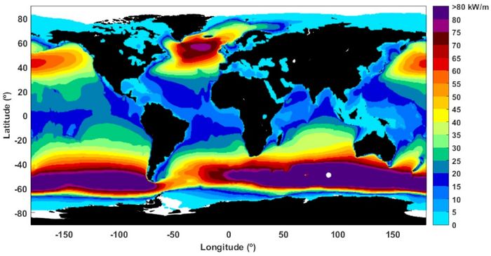
Ocean waves offer a greater consistency and are more predictable than solar or wind energy. Although the variability in wave power levels is large, waves containing harvestable energy are able to generate power up to 90 percent of the time, far outperforming wind or solar power devices[5]. The global distribution of mean wave power over the oceans is shown in Fig.1. Regions with the highest wave power are the Southern Ocean and the North Atlantic. Focusing on the annual wave resource near to the shore, in the Northern Hemisphere, the highest levels are the ones registered in the west coast of the British Isles, Iceland and Greenland. In the Southern Hemisphere, the highest energy levels are found in Southern Chile, South Africa and the entire south and southwest coasts of Australia and New Zealand. Medium levels are located in equatorial waters, with the highest coastal resources of Northern Peru and Ecuador, although El-Nino may induce significant inter-annual variability in this area.
The wave climate strongly fluctuates with high extremes in most regions with a high wave power, especially in the Northern Hemisphere[6]. This places severe requirements on the robustness of the design and the service lifespan of WEC devices, which translate into significant construction and maintenance costs as devices must not only withstand harsh environmental conditions, including severe storms, but also saltwater corrosive effects and biofouling. Areas with a more consistent wave climate and narrow-band wave spectrum may therefore be preferred for wave energy recovery even if the maximum energy yield is somewhat lower. Waves that are practical for conversion are long swells with amplitudes of 2 to 3 meters or less. These types of waves also offer the advantage of producing minimal impact forces, aiding in the survivability of the device[7].
Wave Energy Converters (WECs) convert wave power into electricity. Although attempts to utilize this resource date back to at least 1890, wave power is currently not widely employed[8]. The wave power farms installed worldwide in 2020 totaled some 20 MW [2], of which only a fraction is operational. This is about 5 orders of magnitude less than the 2-3 TW required to exploit the global wave energy potential. An important reason is the production costs per kWh (considering LCoE, Levelized-Cost-of-Energy), which were in 2020 typically a factor of 5-20 higher compared to offshore wind farms. However, it is expected that large scale deployment may result in a considerable cost reduction[9]. Since wave energy cannot (yet) compete with more mature technologies for harvesting renewable energy sources (wind, solar), targeting offshore niche markets could be a realistic strategy to mature and grow the wave energy sector. For example, WECs can serve as nearshore and offshore energy supply stations for mobile platforms at sea (e.g. ships) and for UAVs, buoys and sensors used in aquaculture, navigation and met-ocean[10].
Wave Energy Conversion Principles
In this section the most popular current methods for wave energy conversion are briefly presented. An indication of the efficiency of these methods is presented in Appendix B.
Oscillating Water Columns (OCW)
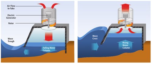
The principle of the oscillating water column is illustrated in Fig. 2, in this example for use in conjunction with a fixed structure (e.g., breakwater). The functioning of the oscillating water columns (OWCs) is somewhat similar to that of a wind turbine, being based on the principle of wave induced air pressurization. The device is set upon a closed air chamber, which is placed above the water while the base is open to the ocean. The passage of waves changes the water level within the closed housing and the rising and falling water level increases and decreases the air pressure within the housing introducing a bidirectional air flow. By placing a turbine on top of this chamber air will pass in and out of it with the changing air pressure levels.
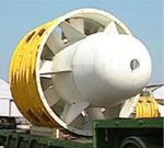
There are two options to separate the bi-directional flow: a Wells turbine to create suction or alternatively, pressure generating valves[12]. The Wells turbine is constructed such that it rotates always in the same direction regardless of airflow direction, see Fig. 3. The efficiency is lower (50-60%) than with conventional turbines, but higher than achievable with conventional turbines in alternating mode[5].
Many studies have been conducted on optimization of the OWC design[13][14][15]. Important design parameters are the air orifice opening (not more than about 1% of the chamber surface) and the draught of the front wall (not larger than necessary). A dual- or triple-chamber OWC performs better than a single-chamber OWC due to a broader effective frequency bandwidth[16].
OWC devices can be moored offshore but they can also be placed near the shore where waves break. This results in significant cost savings. The disadvantage is the shallow water depth along the shore, which dampens the largest waves. This disadvantage can be partly overcome by constructing protruding walls that focus the wave energy towards the OWC. See also Wave energy converters in coastal structures.
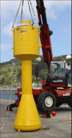
Special buoys have been developed for the application of OWC converters in deep water, according to the principle of Fig. 4. The length of the shaft determines the resonance frequency, allowing optimum energy efficiency to be achieved. An example of an offshore OWC is the Spar Buoy, Fig. 5. The original concept was invented by Yoshio Masuda (1925-2009), who developed navigation buoys powered by wave energy, equipped with an air turbine. Due to the cylindric shape it is invariant to wave direction (Fig. 5). The size varies according to the sea conditions at the deployment site but maximum dimensions are estimated at 30 m diameter, 50 m height and 35 m draft, which could deliver up to 450 kW.
For a review of the development of OWC designs for wave energy conversion the reader may consult Gayathri et al. (2024[17]).
Overtopping Devices
Another type of wave energy converter is the overtopping device, which operates somewhat similar to a hydroelectric dam. The "Wave Dragon" created by Wave Dragon ApS[18] is the best known example of an offshore overtopping device (Fig. 6). Its floating arms focus waves onto a slope from which the wave overtops into a reservoir. The resulting difference in water elevation between the reservoir and the mean sea level then drives low-head hydro turbines. It was estimated that an optimal size design of 260 m width and 150 m length can produce up to 4 MW. In wave climates above 33 kW/m, this technology was expected to be economically competitive with offshore wind power in the near future. After a combined cost saving and power efficiency increase, the power price could eventually be in line with costs of fossil fuel generation[19]. However, a feasibility study for a Wave Dragon deployment at the northern Spanish coast published in 2020 reported costs which were still a factor 10 higher[20].
Near the shore, overtopping converters can be installed in front of or as part of caisson breakwaters. An example is the SeaWave Slot-Cone Generator (SSG)[21], which collects seawater by wave overtopping over several reservoirs placed above each other, resulting in high hydraulic efficiency, see Wave energy converters in coastal structures.
Wave absorbing devices
A great number of different devices have been developed to harness wave energy directly by using wave-induced water motion. The most popular types are displayed schematically in Fig. 7.

Heaving point absorbers
Point absorber are buoy-type wave energy converters (WECs) that harvest incoming wave-energy from all directions. They are placed offshore at the ocean surface or just below. A vertically submerged floater absorbs wave energy which is converted by a piston or linear generator into electricity. The damped vertical motion and power generation of a buoy-type point absorber in a regular wave field is described in Appendix C.
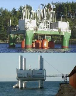
Another type of point absorber is the FO3 concept developed by Norwegian entrepreneur Fred Olsen. It consists of several (12 or 21) heaving floaters attached to a 36 by 36 meter rig (Fig. 8 top). By means of a hydraulic system, the vertical motion is converted into a rotational movement that drives the hydraulic motor. This motor in turn powers the generator that can produce up to 2.52 MW[23].
The multiple point absorber type "Wave Star", developed by Wave Star ApS[24], has a number of floaters on movable arms (Fig. 8 bottom). The energy of the motion of the arms is again captured in a common hydraulic line and converted into electric current. Most noticeably, being able to raise the entire installation along its pillars, this system has a high endurance for rough storm conditions. So far, this method has not been deployed at full scale. A 1:2 scaled installation has been built at Hanstholm which turns out 600 kW. However, production is thought to be scale-able up to 6 MW[25]. A major benefit of these types of exploitation is the minimal contact with water, placing any delicate machinery and electrics out of reach of any corrosion or physical forcing of the waves. The Wave Star development was abandoned in 2016.
Oscillating point absorbers
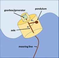
A Vertical Axis Pendulum WEC (VAPWEC)[26] is an oscillating point absorber type device whose power take-off system is based on the motion of an internal pendulum that is connected to a generator, which is all within the device’s hull, see Fig. 9. As the device floats on top of the surface, the pitching and rolling moments due to the incoming waves cause the VAPWEC pendulum to swing around a vertical axis. Advantages of this device type are (1) a robust design since all major components are sealed within the protective hull and (2) the simplistic energy conversion design, which has minimal moving parts and power take-off system that has few hard stops. Several other wave energy converters use a similar principle, for example the SEAREV that uses an internal pendulum wheel[27], the ISWEC that uses a gyroscope[28] and the HRWEC that uses a flap[29]. A similar design (oscillating half cylinder or half sphere) is used by E-Motions, where the wave-induced roll oscillations of the hull are damped by a power take-off system that consists of sliding (tribo)electrical elements[30].
Terminators
Terminators consist of flaps that rotate with the wave orbital motion around an axis parallel to the wave front. They are also called oscillating surge converters as they exploit the surging wave motion. Examples are the Oyster (Fig. 10a) and the WaveRoller(Fig. 10b), both bottom-hinged terminators and the Salter Duck (Fig. 10c), with a rotation axis near the surface. Although these designs capture wave energy with a high efficiency (see Appendix B), no large-scale operational deployments have been realized. They are installed in intermediate depths, not far from the shore, where the wave front direction is most of the time close to shore-parallel. Oyster and WaveRoller have been tested in nature; for Salter Duck no full-scale prototype was built. Oyster’s electrical output is generated by an hydro-electric turbine onshore, driven by high pressure water via subsea pipelines. WaveRoller is equipped with an on board hydraulic system that drives an electricity generator, which is connected to the electric grid via a subsea cable. Hinged wave surge converters generally use hydraulic systems for power take-off (PTO). Hydraulic systems are well suited to harvest energy from high-force, slow-oscillatory motions which have to be converted to rotary motion and drive a generator. In order to rectify the fluctuating wave power, which would result in variable electrical power output unsuited to the electrical grid, some sort of energy storage system (or other means of compensation, such as an array of devices) is usually incorporated in the PTO system, such as accumulators, which can function as short term energy storage, helping the system handle the fluctuations[5].
Wave attenuators
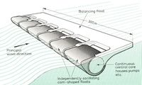
These devices lie parallel with the incident wave direction. The "DEXA", developed and patented by DEXA Wave Energy ApS [31], is an illustrative example of a wave attenuator. The device consists of two hinged catamarans that pivot relative to the other (Fig. 11). The resulting oscillatory flux at the hinge is harnessed by means of a water-based low pressure power transmission that restrains angular oscillations. Flux generation is optimized by placing the floaters of each catamaran half a wavelength apart. A scaled prototype (dimensions 44x16.2m[32]) placed in the Danish part of the North Sea should generate 160 kW[33]. Full-scale models are thought to be able to generate up to 250 kW[31]. However, the DEXA development was terminated in 2012. Another example of this type of device is the 750 kW Pelamis, consisting of five tube sections linked by universal joints which allows for flexing in two directions as the device 'rides' over the incoming waves. The flexing movement is converted into electricity via hydraulic power take-off systems.
Power take-off systems (PTO)
The objective of WECs is to convert the kinetic energy from incident waves to compatible electrical energy that can be integrated into the utility grid. Extracting the maximum energy from a WEC system is a key challenge. A WEC device generally contains two controller systems: the primary controller for the power take-off (PTO) and the secondary controller for the grid power converter. The secondary controller regulates the voltage, current, and frequency to make sure it can be integrated into the power grid. The primary controller aims to maximize the harvesting of electrical energy from the wave-generated mechanical device motions. For wave-absorbing devices, this can be achieved by phase matching, allowing the WEC to enter a resonant state, amplify its motion, and absorb more energy.
Optimal performance is achieved when the PTO force [math]f_{PTO}(t)[/math] is controlled such that the absorbed power [math]P_{PTO} = \int v(t) f_{PTO}(t)dt[/math] is optimized. Here [math]f_{PTO}[/math] is the damping force exerted by the PTO and [math]v[/math] is the buoy velocity. Controlling the PTO to realize optimal performance requires future knowledge of the excitation force. While this knowledge is straightforward for regular waves, it is much more complex for irregular seas[34]. Instead, a suboptimal approach is often used, where the instantaneous value of the PTO force is linearly proportional to the oscillating body speed, [math]f_{PTO}(t) = b_{PTO} \, v(t)[/math], where [math]b_{PTO}[/math] is the PTO damping coefficient (see Appendix C).
The majority of power produced by WEC devices occurs during resonant absorption when the excitation force is in phase with device velocity. When the wave climate does not match the structurally defined resonance of the device, the power produced is significantly smaller. A popular control mechanism is called 'latching'. It consists of temporary locking and then releasing the WEC to bring it into resonance with the incident wave[35]. This mechanism is most effective when the incoming waves have a period greater than the resonance period of the oscillating body. Another type of PTO control strategy is known as model predictive control (MPC), which aims to optimize the system performance by predicting the excitation force. Various MPC algorithms have been developed for model predictive control[36][34]. These algorithms requires large computation power for real-time implementation.
Another function control systems offer is their ability to limit the mechanical forces by damping and tuning the device motion, providing improved device survivability and potentially lower maintenance costs. For highest power extraction, damping must be adjusted to achieve maximum energy conversion efficiency. If the damping is too high then the motions are limited and little power is produced. If the damping is too light, then the damper absorbs little power and little power is taken off. With any PTO system, the correct damping is vital for an efficient system[5][37]. Active device tuning can range from adjusting parameters of the primary converter for a particular sea state to wave-by-wave adaptation (also known as fast tuning).
The power take-off (PTO) system of a wave energy converter has a direct impact on the capital cost of a project by usually accounting for between 20 and 30% of the overall investment. The economic viability, efficiency and complexity of a wave energy converter depends largely on its PTO system. Maintenance at sea is a demanding and expensive task; high reliability and durability of all components of the PTO system are therefore required. This is technically challenging for systems exposed to the harsh marine environment, especially systems that consist of many moving parts that are exposed to corrosion and fouling. Several popular PTO systems have been reviewed by Ahamed et al. (2020[37]) and Yang et al. (2024[38]), from which the summary below is extracted.
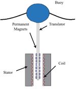
Oscillating water column wave converters (OWC) generally use the previously described Wells turbine as PTO system. These turbines are vulnerable due to the relatively large number of moving parts and the energy conversion efficiency is relatively low. Overtopping devices are generally equipped with hydro turbines for power take-off. Conventional hydro turbines require for high efficiency more head and flow than provided by overtopping ocean waves. Wave absorbing devices use hydraulic motor systems or direct mechanical or electrical drive PTO systems. Hydraulic motor-based PTO systems are suited for converting the low-speed oscillating motion into energy. However, the hydraulic motor-based PTO system consists of many mechanical moving parts and due to compression and decompression of the fluid there is a risk of hydraulic oil leakage. Maximum power output and maintaining system stability can be accomplished by employing advanced control strategies on key components of the PTO, e.g. the hydraulic cylinders, valves, accumulators, hydraulic motors and generators. Direct mechanical drive uses linear-to-rotary conversion systems without pneumatic or hydraulic systems. The efficiency is high, but the lifetime is relatively short and maintenance costs are substantial. Direct electrical drive transmits the wave energy into electrical energy directly by coupling the mechanical energy to the moving part of a linear generator (Fig. 12). Issues are the need for a heavy structure due to the attractive forces between the stator and the translator and the complicated power transmission system due to the unequal generated voltage created by the irregular wave motion. To smooth out the power fluctuations of such a direct-drive WEC, energy storage components such as batteries, supercapacitors, or a hybrid combination of the two can be employed to stabilize the generated power.
The 'Triboelectric nanogenerator' (TENG) and its extension, the 'Triboelectric−Electromagnetic Hybrid Nanogenerator' (TENG-EMG)[39], are a new development that can efficiently harvest energy in any frequency range, are low-cost lightweight, easy to fabricate and easy to be scaled (size of individual units being below the micrometer scale). The nanogenerator uses a polymer-metal pair to create contact electrification (triboelectric effect) between two materials sliding against each other and to induce charge transfer between their electrodes due to electrostatic induction, either in a layer structure or in a spherical-shell structure[40], see Fig. 13. However, several issues still need to be resolved to enable large-scale application in practice. These include: lifetime of the material due to wearing, low surface charge density, inefficient energy extraction due to high voltage and low current and connection methods of the thousands of TENG units that are needed[41].

Issues with wave energy converters
To be able to produce energy at competitive prices, several obstacles have to be overcome. The following factors in particular determine the high costs of wind energy.
A very robust construction made of high-quality materials is required that remains intact under severe storms and withstands the demanding conditions at sea leading to corrosion, fouling and fatigue. The classical protection measure against fouling and corrosion of steel structures is regular maintenance and repainting. But this is time-consuming and costly because of the difficult access to offshore installations, especially under harsh conditions when damage occurs. In addition, the use of antifouling paints may be detrimental to the marine environment (e.g., Tributyltin paints[42]). The performance of the installation may suffer not only from colonization by microorganisms, but also from attracting fish and other marine mammals and seabirds that feed on fish. The cost of repairs is a major component of the wave farm costs. The reliability of the components, especially due to the cost of eventual repair actions, is pivotal for the economic viability of a project[43]. Deployments should be capable of lasting 30 years or more. This is a tall order as demonstrated by the mooring of the Wave Dragon that failed after two years deployment during a severe storm on the 8th of january 2004.
The power generated by ocean waves fluctuates strongly due to the irregular wave climate, which makes connection to the electricity grid difficult[44]. In addition, connection points to the electricity grid may not be available in areas where the conditions for wave energy generation are most favorable.
Crucial for any design is the mooring which ensures a maintained position under both normal operating loads as well as extreme storm load conditions. It should not exert excess tension loads on the electrical transmission cables and ensure the suitable safety distances between devices in multiple installations. Most commonly, a free hanging catenary configuration is used for mooring but multi-catenary systems and flexible risers are also utilized. The mooring configuration should be sufficiently compliant to accommodate tidal variations and environmental loading while remaining sufficiently stiff to allow berthing for inspections and maintenance. Variations in wave directionality in deep waters also pose a challenge for device power generation. It is essential that wave devices (also arrays of wave devices and nonaxisymmetric devices) are able to align themselves accordingly on compliant moorings that allow them to absorb energy from any direction.
Due to the great variability of the wave climate with incidental extremes, it is important to be able to test prototype designs over a long period before they are deployed on a large scale. Mathematical simulation models can be of great value here, because this is a quick and relatively inexpensive way to test a design for its effectiveness and efficiency at the long term, both in terms of capital and operational expenses, in order to achieve the lowest overall cost of electricity. For this purpose, the modeling tool supports the decision-maker in the pursuit of the most reliable and easy-to-maintain device design and also informs about the trade-off between energetic yield and operational and maintenance efforts[43].
The power take-off system is a crucial part of wave energy converters, which largely determines the cost, efficiency and reliability of the WEC. Many studies focus on optimisation of the PTOs; several challenges related to PTOs are mentioned in the previous section.
Wave energy converters combined with offshore wind
The high cost of stand-alone wave energy conversion schemes is a major obstacle for its large-scale application. However, costs can be significantly reduced by combining WECs with structures offshore or along the coast that are being built for other applications. A good example is the integration of WECs with breakwaters in the coastal zone. This is described in the article Wave energy converters in coastal structures.
Another possible combination is the integration of wind and wave energy production. This is especially interesting in areas where the conditions for optimal wind energy production do not systematically coincide with conditions for optimal wave energy production. It is also a way to make optimal use of marine space[45]. The main advantage of integrated wind power generation is shared infrastructure costs, especially foundations and grid connections. Hybrid power generation architectures that integrate WEC with offshore wind turbine generators or energy storage systems can be a promising solution for power quality improvement and sustainable electric power production. However, with the existing WEC techniques, the costs per kWh produced are still higher with a combined wind-wave application than with wind energy alone[46]. Synergy benefits can also be sought through improved stability of the structure, for example in the case of an OWC wave energy converter integrated into an offshore wind turbine monopile[47]. Stability improvement can be a major benefit for designs in which the interaction between the wind and wave sub-structures is strong, as in the case of a WEC combined with a floating wind turbine[48][49]. Wave energy converters can also reduce wave heights inside a wind farm, increasing in this way the weather windows to access the wind turbines[50].
International organizations
Several organizations have been established for worldwide collaboration on ocean wave energy development involving research institutes, wave energy developers, operators and governments.
Ocean Energy Europe (OEE), a not-for-profit organization, is a network of ocean energy professionals collaborating with 120 organizations, including Europe’s top utilities, industrialists and research institutes. It aims to create a strong environment for the development of ocean energy, improve access to funding, and enhance business opportunities for its members. To this end, OEE engages with the European Institutions (Commission, Parliament, Council, EIB, etc.), and national ministries on policy issues affecting the sector. Ocean Energy Europe also organizes the annual Ocean Energy Europe Conference and Exhibition – the annual event which gathers representatives from the industry, Ministers and Commissioners.
The Ocean Energy Systems Technology Collaboration Programme (OES), established by the International Energy Agency (IEA), is an international organisation that is actively collaborating between its 29 member countries with the aim of advancing ocean energy research, development and demonstration of technologies to generate electricity from ocean energy resources (Wave, Tidal Range, Tidal and Ocean Currents, Ocean Thermal Energy Conversion (OTEC) and Salinity Gradients). The primary education and research initiatives of OES are aimed at promoting the feasibility, recognition and adoption of ocean energy systems in an environmentally acceptable manner.
The European Marine Energy Centre (EMEC) Ltd provides developer companies, wave and tidal energy converter-technology developer with certified open-sea testing services. The objective of EMEC is to decrease the time, cost, and risk related with marine energy technology development, increasing the use of EMEC’s modified facilities as well as industry knowledge and other experiences. EMEC has 13 grid connected test berths where many marine energy converters have been installed. EMEC is an independent organization that maintains relations with various developer companies, academic organizations and governing bodies and presently working with companies and researchers to broaden research programmes to solve a variety of environmental and operational challenges relevant to industry.
The European Network for marine renewable energy (WECANet) is a network of 31 partner countries to assist networking, training and collaboration in Europe. Four working groups address the following topics: numerical modelling for WECs, experimental hydrodynamic modelling including PTO systems, technology development and economical / political aspects.
OCEANERA-NET organizes funding programmes to support research and innovation between European countries and regions in the ocean energy sector.
International conferences on ocean energy are organized by
- European Wave and Tidal Energy Conference (EWTEC). Selected peer-reviewed conference contributions are published in the EWTEC’s International Marine Energy Journal.
- Asian Wave and Tidal Energy conference (AWTEC) addresses updates on recent global activities and initiatives with a distinctly special interest in the Asian region. The conference cooperates with the Journal of Marine Science and Engineering for publication of selected conference contributions.
- International Conference on Ocean Energy (ICOE) is a biennial global marine energy event focused on the industrial development of renewable marine energy. ICOE is a collaboration with the IEA Technology Collaboration Programme – Ocean Energy Systems (OES).
Related articles
External links
Further reading
- Drew, B., Plummer, A.R.and Sahinkaya, M.N. 2009. A review of wave energy converter technology. Proceedings of the Institution of Mechanical Engineers, Part A: Journal of Power and Energy 223(8): 887-902 [3]
For an overview of the current status and recent technological developments of Wave Energy Converters, the reader is referred to the publications:
- Ahamed, R., McKee, K. and Howard, I. 2020. Advancements of wave energy converters based on power take off (PTO) systems: A review. Ocean Engineering 204, 107248
- Aderinto, T. and Li, H. 2018. Ocean Wave Energy Converters: Status and Challenges. Energies 11, 1250; doi:10.3390/en11051250 (open access)
- Zhang, Y., Zhao, Y., Sun, W. and Li, J. 2021. Ocean wave energy converters: Technical principle, device realization, and performance evaluation. Renewable and Sustainable Energy Reviews 141, 110764
- Lopez, I., Andreu, J., Ceballos, S., Martínez de Alegría, I., Kortabarria, I. 2013. Review of wave energy technologies and the necessary power-equipment. Renewable and Sustainable Energy Reviews 27: 413–434
Appendix A: Wave energy resource assessment
Wave resource assessment is an essential component of the planning process of wave energy exploitation[51]. The assessment consists mainly of the characterization of dominant metocean conditions (e.g., wind, wave, current and water level) and the energy potential. This information can be obtained from wave stations in areas where they are deployed. In situ data can be complemented with satellite altimeter observations, despite spatial and temporal limitations. The exploitation of satellite data requires inversion models to estimate the wave period and the wave power density in offshore waters. Using numerical hindcast databases and reanalysis archives is an alternative. They are available in most energetic shelf sea environments around the world. However, recorded sea wave characteristics are generally restricted to integrated parameters such as the significant wave height and wave period, without detailed assessment of the wave energy spectrum or the available wave energy flux. Simulations with numerical hydrodynamic models can provide direct information on the wave energy density by computing the evolution of the wave energy spectrum in spatial, frequency and directional spaces. The interaction with tidal currents should be included to refine the numerical assessments of the wave energy resource in areas with large tidal ranges. Simulations should cover a period of at least ten years, using archives of historical weather observations or hindcast databases[51].
A short introduction to wave resource assessment is given below.
For regular water waves, the time-mean wave energy density [math]E[/math] per unit horizontal area on the water surface [J/m2] is the sum of kinetic and potential energy density per unit horizontal area. The potential energy density is equal to the kinetic energy [52] both contributing half to the time-mean wave energy density [math]E[/math] that is proportional to the wave height squared according to linear wave theory [52] (see Shallow-water wave theory):
[math]E= \large\frac{1}{8}\normalsize \rho g H^2 , \qquad (1)[/math]
where [math]g[/math] is the gravity acceleration and [math]H[/math] the wave height of regular water waves. As the waves propagate, their energy is transported. The energy transport velocity is the group velocity. As a result, the time-mean wave energy flux per unit crest length [W/m] perpendicular to the wave propagation direction, is equal to [52]:
[math] P = E \times c_{g} , \qquad (2)[/math]
with [math]c_{g}[/math] the group velocity [m/s]. Due to the dispersion relation for water waves under the action of gravity, the group velocity depends on the wavelength [math]\lambda[/math] [m], or equivalently, on the wave period [math]T [/math][s]. Further, the dispersion relation is a function of the water depth [math]h[/math] [m]. As a result, the group velocity behaves differently in the limits of deep water ([math]h \gt \lambda / 2[/math]), shallow water ([math]h \lt \lambda/20[/math]), and at intermediate depths ([math]\lambda /20 \lt h \lt \lambda / 2[/math]). For regular waves in deep water
[math]c_{g} = \large\frac{gT}{4\pi}\normalsize [/math] and [math]P_{w1} = \large\frac{\rho g^2}{32 \pi}\normalsize H^2 T . \qquad (3)[/math]
The time-mean wave energy flux per unit crest length is used as one of the main criteria to choose a site for wave energy converters. For real seas, whose waves are random in height, period and direction, the spectral parameters have to be used (for the definition of spectral wave parameters, see the article Statistical description of wave parameters). The spectral estimate of significant wave height [math]H_{m0}[/math] is calculated from the zero-order moment of the spectral function [math]m_0[/math] according to [math]H_{m0} = 4 \sqrt{m_0} [/math]. The relevant wave period is the mean energy period [math]T_E \equiv T_{m-1,0}[/math] [53],
[math]P_{w1} = \large\frac{\rho g^2}{64 \pi}\normalsize H_{m0}^2 T_E . \qquad (4)[/math]
If local data are available for a sea state ([math]H_{m0}^2, T_E [/math]) through in-situ wave buoys, satellite data or numerical modelling, Eq. (4) provides a first estimate of the wave energy flux. Averaged over a season or a year, it represents the maximal energetic resource that can be theoretically extracted from wave energy. If the directional spectrum of sea state variance [math]E(f,\theta)[/math] is known with [math]f[/math] the wave frequency [Hz] and [math]\theta[/math] the wave direction [rad], a more accurate formulation is used:
[math]P_{w2} = \rho g\int\int c_{g}(f,h)E(f,\theta) dfd \theta . \qquad (5)[/math]
Equation (5) can be reduced to (4) with the hypothesis of regular waves in deep water. The directional spectrum is deduced from directional wave buoys, SAR images or advanced spectral wind-wave models, known as third-generation models, such as WAM, WAVEWATCH III, TOMAWAC or SWAN. These models solve the spectral action balance equation without any a priori restrictions on the spectrum for the evolution of wave growth.
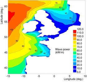
The nearshore wave atlas ANEMOC along the Atlantic coast of Europe is based on numerical simulation with the TOMAWAC model of the wave climate over 25 years[55]. Using equation (5), the time-mean wave energy flux along West European coasts is obtained, shown in Fig. 14. This equation still presents some limits like the definition of the bounds of the integration. Moreover, getting data on the wave energy near coastal structures requires the use of numerical models that are able to represent the physical processes of wave transformation in shallow or intermediate water due to refraction, shoaling, dissipation by bottom friction or by wave breaking, interactions with tides and diffraction by islands.
The wave energy flux is therefore usually calculated for water depths superior to 20 m. This maximal energetic resource calculated in deep water will be limited in the coastal zone:
- at low tide, by wave breaking;
- at high tide during storm events, when the wave height exceeds the maximal operating conditions;
- by screen effects due to the presence of capes, spits, reefs, islands,...
The total European wave energy resource is estimated in the range 1000-1500 TWh/yr[56].
Appendix B: Efficiency of wave energy conversion methods
Buoys that generate energy by going up and down with the wave motion, the so-called point absorbers, are the most common wave energy conversion systems in deep water (see section point absorbers). The energy yield is greatest when the buoy's resonance frequency is equal to the wave frequency. A theoretical model, which only applies to small monochromatic waves, shows that the maximum power [math]P_{max}[/math] [W] that a point absorber can generate in such a wave field is given by the product of the average wave energy flux per unit crest length [math]P_w[/math] [W/m ] divided by the wavenumber [math]k=2 \pi / \lambda [/math] [1/m][57]. This means that the size of the point absorber does not really matter. Unfortunately, the practice is less favorable, on the one hand because the strong variability that is characteristic for sea conditions makes that resonance only occurs in exceptional cases, and on the other hand because the greatest energy output does not correspond to small wave amplitudes. The capture width ratio [math]\eta[/math] of wave energy converters is defined as
[math]\eta = \Large\frac{P}{B P_w}\normalsize , \qquad (B1)[/math]
where [math]P[/math] is the average energy absorbed by the device and [math]B[/math] a representative width of the device (or length in the case of attenuators). The capture width ratios achieved by prototype models of the different types of wave energy converters are in the following ranges[58]:
- Oscillating water column devices 15-40% (typical width [math]B \sim[/math] 30 m)
- Overtopping devices 4-23% (typical width/length [math]B \sim[/math] 300 m)
- Point absorbers 3-42% (typical width/length [math]B \sim [/math] 5-20 m; the lower percentages are for the smaller devices)
- Terminators 41-65% (typical width/length [math]B \sim [/math] 20 m)
- Floating pitching devices 20-36% (typical width/length [math]B \sim[/math] 25 m)
- Attenuators 5-7% (typical length [math]B \sim [/math] 150 m)
Appendix C: Linear model of the heaving buoy WEC
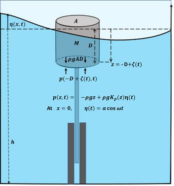
Here we illustrate wave energy conversion by considering a strongly simplified linear model of the constrained vertical motion [math]\zeta(t)[/math] of a cylindrical buoy forced by the sinusoidal motion [math]\eta(x,t)=a e^{i \omega t}[/math] of the sea surface, see Fig. C1. For convenience of notation we use complex variables, only the real part being relevant.
The motion of the buoy is described by the heave equation (Archimedes' law):
[math]M \, \Large\frac{\partial^2 \zeta}{\partial t^2}\normalsize = - \rho g \, A \, D + A \, p(z,t) - Dissipation \, (Radiation + Drag) - F_{PTO} , \quad z = -D + \zeta(t) . \qquad (C1)[/math]
Meaning of the symbols: [math]M=[/math] mass of the buoy, including the mass of surrounding fluid accelerated by the buoy, [math]A=[/math] buoy section area, [math]D=[/math] buoy draft, [math]p=[/math] pressure, [math]h=[/math] water depth, [math]a=[/math] wave amplitude, [math]\omega=[/math] radial wave frequency, [math]k=[/math] wave number, [math]\rho=[/math] seawater density, [math]g=[/math] gravitational acceleration. It is assumed that the buoy dimensions are much smaller than the wavelength, in which wave scattering can be neglected[59]. The PTO dissipation term [math]F_{PTO}[/math] represents the energy damping caused by the Power Take Off system (in this case a linear electrical generator). The dissipation by fluid drag represents the energy loss related to the generation of turbulent motions by the moving buoy. The radiation dissipation is the energy loss related to the generation of outward radiating waves by the moving buoy. It is assumed, as a rough approximation, that the dissipation terms can be represented by the linear parametric form[59]
[math]\; Dissipation \, (Radiation + Drag) = b \, M \, \omega \dfrac{\partial \zeta}{\partial t} \, , \quad F_{PTO}=b_{PTO} \, M \, \omega \, \dfrac{\partial \zeta}{\partial t} \; , \qquad (C2)[/math]
where [math]b[/math] and [math]b_{PTO}[/math] are dimensionless parameters. The parameter [math]b[/math] can be estimated from numerical hydrodynamic models or from experimental prototype tests.
According to linear wave theory (see Shallow-water wave theory),
[math]p(z)=p(-D+\zeta,t) = \rho g \, D - \rho g \, \zeta + \rho g \, a \, K_p(-D+\zeta) \, \cos \omega t , \qquad (C3)[/math]
where [math]K_p(z) = \Large\frac{\cosh(k(h+z))}{\cosh(kh)}\normalsize . [/math]
If the buoy draft is much smaller than the water depth, [math]D-\zeta \lt \lt h[/math], we have [math]K_p (D-\zeta) \approx 1[/math].
The dissipation terms dampen the free oscillations of the buoy and cause a phase shift [math]\phi[/math] with respect to the wave motion. Due to the linearity of Eq. (C1), the vertical motion of the buoy will have the parametrization (C2) of the dissipation.
[math]\zeta(t) = \zeta_0 \, e^{i \omega t} \, , \; \zeta_0 = |\zeta_0| \, e^{ - i \phi} \, . \qquad (C4)[/math]
Substitution in Eqs. (C1) and (C2) gives
[math]\zeta_0 = a \, \Big[ -m+1 +i \, m (b+b_{PTO}) \Big]^{-1} \, , \quad m = \Large\frac{M \omega^2}{\rho g A}\normalsize \, . \qquad (C5)[/math]
The amplitude and phase shift are given by [math]\quad |\zeta_0| = \Large\frac{a}{\sqrt{(1-m)^2 + m^2 (b+b_{PTO})^2}}\normalsize \, , \quad \tan \phi = \Large\frac{bm}{1-m}\normalsize. \qquad (C6)[/math]
The average power (=buoy velocity x force ) transferred to the PTO is given by
[math]P_{PTO} = b_{PTO} \, M \, \omega \Large\lt [ \frac{\partial \zeta}{\partial t} ]^2 \gt \normalsize = \dfrac{a^2 \, \omega^3 \, M \, b_{PTO}}{2 \big[(1-m)^2+ m^2 (b+b_{PTO})^2 \big]} \, . \qquad (C7)[/math]
The transferred power is greatest if the buoy dimensions (draft, surface) and density are chosen such that the buoy motion is close to resonance most of the time, meaning [math]m \approx 1[/math] for the peak frequency of the wave field. In this case [math]\quad P_{PTO} = \dfrac{a^2 \, \omega^3 \, M \, b_{PTO}}{2 (b+b_{PTO})^2} [/math]
The transferred power is highest if the PTO is tuned such that [math]b_{PTO} = b [/math], giving [math]\quad P_{PTO} = \dfrac{M a^2 \omega^3}{8 b} \, . \qquad (C8)[/math].
This maximal transferred power can also be achieved if the buoy dimensions are such that [math]m \ne 1[/math]. In this case, the power take-off force [math]F_{PTO}[/math] has to be adjusted such that it has a phase delay [math]\psi[/math] relative to the buoy velocity [math]\partial \zeta / \partial t[/math]. Substitution of [math]\quad F_{PTO}=b_{PTO}\, M \, \omega \dfrac{\partial \zeta}{\partial t}\, e^{- i \psi} \quad[/math] in Eq. (C1) gives
[math]\zeta_0 = a \, \Big[ -m+1+m \, b_{PTO} \sin \psi +i \, m \, (b+b_{PTO}\cos \psi) \Big]^{-1} \, . \qquad (C9)[/math]
The average transferred power is now given by [math]\quad P_{PTO} = \frac{1}{2} b_{PTO} M \omega^3 |\zeta_0|^2 \cos \psi[/math].
It can easily be verified that the maximum value of [math]P_{PTO}[/math] given by Eq. (C8) is obtained for [math]\; -m+1+m \, b_{PTO} \sin \psi =0 \;[/math] and [math]\; B_{PTO}\cos \psi =b \;[/math], thus
[math]\quad b_{PTO}=b \, \sqrt{1+\Big( \dfrac{m-1}{m} \Big)^2 } \, , \quad \tan \psi = \dfrac{m-1}{bm} \, , \quad \zeta_0 = - \dfrac{i a}{2 m b} \, . \qquad (C10)[/math]
The same result is found when the Optimal Control Theory is applied to the linear heaving buoy equations[60].
Tuning the power take-off function to this optimum implies that the transferred power is optimal only for a single wave frequency. The optimal power transfer can therefore not be achieved in this way for the irregular wave fields occurring in practice. To increase the power transferred in irregular wave fields, various control strategies have been devised, for example the latching method discussed in section #Power take-off systems (PTO).
Budal and Falnes (1977[61]) have established limits for the maximum power than can be extracted by point absorbers from a regular sinusoidal wave field.
The condition that a WEC buoy may not jump out of the water or become totally submerged at resonance, implies [math]\zeta_0 \approx \Large\frac{a}{b}\normalsize \lt \zeta_{max} = \large \frac{1}{2}\normalsize D[/math] or [math] b \gt \Large \frac{2a}{D}\normalsize[/math]. Therefore, [math]M \omega b = b_{PTO}+b_{drag}+b_{rad} = 2 (b_{drag}+b_{rad}) \gt M \omega \Large \frac{2a}{D}\normalsize [/math].
The maximum wave power transmitted to the PTO is thus given by [math]P_{PTO, max} = \large \frac{1}{8}\normalsize \omega^3 M D a = \large \frac{1}{8}\normalsize \rho \omega^3 A D^2 a . \qquad (C11)[/math]
The power absorbed by the buoy is the product of the excitation force [math]F_e = \rho g A a \cos \omega t[/math] and the buoy speed [math]u = - \partial \zeta / \partial t[/math]. The maximum boy speed is [math]u_{max} = \omega \zeta_{max} \sin(\omega t - \phi) = \large \frac{1}{2}\normalsize \omega D \sin(\omega t - \phi) [/math]. An upper limit of the absorbed wave power averaged over the wave cycle, the so-called Budal limit, is thus given by
[math]P_{Budal} = \large \frac{1}{4}\normalsize \rho g \omega V a , \qquad (C12)[/math]
where [math]V = DA = \pi D R^2[/math] is the submerged buoy volume. [61] The difference with Eq. (C11) is that the Budal limit does not make an assumption about the parametrization of the dissipation term (C2).
The incident wave power is given by [math]P_w= ½ \rho \,g \, c_g \, a^2[/math]. The energy propagation speed [math]c_g[/math] is approximately equal to half the wave propagation speed in deep water, [math]c_g \approx \omega / (2 k)[/math], where the wave number [math]k = 2 \pi / \lambda[/math] and [math]\lambda[/math] is the wavelength. The Budal upper limit of the capture width ratio [math]\eta_{Budal}[/math] is thus given by
[math]\eta_{Budal} = \large\frac{P_{Budal}}{2 R P_w}\normalsize = \large\frac{k V}{2 R a}\normalsize = \large\frac{\pi^2 D R }{a \lambda}\normalsize . \qquad (C13)[/math]
A second theoretical upper limit of the wave energy that can be absorbed by a cylindrical heaving buoy corresponds to a buoy design such that the waves radiated from the moving buoy precisely annihilate the undisturbed outgoing cylindrical waves[61]. This limit (which is never reached in practice) is given by [math]\eta_{max} \approx 1 / (2 \, k\, R) = \lambda / (4 \pi R)[/math]. The proof is as follows[62].
The wave energy flux (wave power) per unit wave crest length towards the buoy is given by (see Shallow-water wave theory)
[math]P_w = ½ \rho c _g g a^2 = \Large\frac{\rho c_g}{g}\normalsize \lt \Large | \frac{\partial\Phi(x, z=0, t)}{\partial t} |^2 \normalsize \gt ,\qquad (C14) [/math]
where [math]c_g[/math] is the wave group velocity. The velocity potential [math]\Phi(x,z=0,t)[/math] for a plane sinusoidal propagating wave is given by
[math]\Phi(x, z=0, t) = \Large\frac{g a}{2 \omega}\normalsize e^{i(kx - \omega t)} + c.c. , \qquad (C15)[/math]
where [math]c.c.[/math] is the complex conjugate and [math]k[/math] is the wave number. This velocity potential can be written as the sum of a set of incoming radial waves and a set of outgoing radial waves,
[math]\Phi = \sum_{n=0}^{\infty} (\Phi_{IN,n}+\Phi_{OUT,n}), \quad \Phi_{IN,n} = \Large\frac{g a}{4 \omega}\normalsize e^{ i (n \pi /2 - \omega t)} \epsilon_n H_n^{(2)}(kr) \cos(n \theta) + c.c., \quad \Phi_{OUT,n} = \Large\frac{g a}{4 \omega}\normalsize e^{ i (n \pi /2 - \omega t)} \epsilon_n H_n^{(1)}(kr) \cos(n \theta) + c.c. , \qquad (C16)[/math]
where [math]r[/math] is the radial distance to the buoy, [math]\theta[/math] is the radial angle, [math]\epsilon_0=1, \; \epsilon_n=2, n \ge 1[/math], and where [math]H_n^{(1)}, H_n^{(2)}[/math] are the Hankel functions of the first and second kind, respectively. An axisymmetric buoy can only absorb axisymmetric wave components, meaning that components [math]n \ge 1[/math] play no role. The optimal wave absorption by the buoy corresponds to the situation where the waves radiated from the moving buoy annihilate precisely the undisturbed outgoing radial waves [math]\Phi_{OUT,0}[/math]. If the buoy shape and dimensions are adjusted to the incident wave field such that this is the case, then the absorbed wave power equals the wave power of the incoming radial wave component [math]n=0 [/math], which is given by
[math]P_{IN} = \Large\frac{\rho c_g}{g}\normalsize \lt \Large | \frac{\partial\Phi_{IN,0}}{\partial t} |^2 \normalsize \gt . \qquad (C17)[/math]
The total incident energy wave energy [math]P_{TOT}[/math] is given by the integral of [math]P_{IN}[/math] over any circular contour around the buoy. Considering a circle of radius [math]r[/math] much larger than [math]1/k[/math], one may approximate
[math]|H_n^{(2)}(kr)|^2 \approx \Large\frac{2}{\pi k r}\normalsize . \qquad (C18)[/math]
The result of integrating [math]P_{IN}[/math] along the far field circle of radius [math]r[/math] over the angle [math]0 \le \theta \lt 2 \pi[/math] yields
[math]P_{absorbed} = P_w / k . \qquad (C19)[/math]
A similar derivation can be made for WECs with other symmetry characteristics. For example, a terminator WEC that is oscillating with the wave orbital motion can only absorb energy from the incoming radial wave component [math]n=1[/math]; wave components [math]n \ne 1[/math] play no role. Integrating the [math]n=1[/math] wave contribution to [math]P_{IN}[/math] along a circular far field contour gives [math]P_{absorbed} = 2 P_w / k[/math], which is twice as much as for an axisymmetric heaving buoy. Generally speaking, a heaving buoy has a lower energy capture ratio than point absorbers with more degrees of freedom. However, due to the relatively simple realization it performs reasonably well from a cost-economic point of view[63]. The power extraction can be significantly increased when the WEC is placed in front of a reflecting structure (e.g. breakwater)[64].
References
- ↑ Guo, B. and Ringwood, J.V. 2021. Geometric optimisation of wave energy conversion devices: A survey. Applied Energy 297, 117100
- ↑ Pelc, R. and Fujita, R.M. 2002. Renewable energy from the ocean. Marine Policy, 26: 471-479.
- ↑ 3.0 3.1 Lewis, A., Estefen, S., Huckerby, J., Musial, W., Pontes, T. and Torres-Martinez, J. 2011. Ocean Energy. In IPCC Special Report on Renewable Energy Sources and Climate Change Mitigation [O. Edenhofer, R. Pichs-Madruga, Y. Sokona, K. Seyboth, P. Matschoss, S. Kadner, T. Zwickel, P. Eickemeier, G. Hansen, S. Schlömer, C. von Stechow (eds)], Cambridge University Press, Cambridge, United Kingdom and New York, NY, USA.
- ↑ Rusu, L. and Rusu, E. 2021. Evaluation of the Worldwide Wave Energy Distribution Based on ERA5 Data and Altimeter Measurements. Energies 14, 394
- ↑ 5.0 5.1 5.2 5.3 Drew, B., Plummer, A.R. and Sahinkaya, M.N. 2009. A review of wave energy converter technology. Proceedings of the Institution of Mechanical Engineers, Part A: Journal of Power and Energy 223(8): 887-902
- ↑ Lopez, I., Andreu, J., Ceballos, S., Martínez de Alegría, I., Kortabarria, I. 2013. Review of wave energy technologies and the necessary power-equipment. Renewable and Sustainable Energy Reviews 27: 413–434
- ↑ Fairley, I., Lewis, M., Robertson, B., Hemer, M., Masters, I., Horrillo-Caraballo, J., Karunarathna, H. and Reeve, D.E. 2020. A classification system for global wave energy resources based on multivariate clustering. Applied Energy 262, 114515
- ↑ Miller, C. 2004. A Brief History of Wave and Tidal Energy Experiments in San Francisco and Santa Cruz. [1]
- ↑ IRENA and OEE 2023. Scaling up investments in ocean energy technologies, International Renewable Energy Agency, Abu Dhabi
- ↑ Clemente, D., Rosa-Santos, P. and Taveira-Pinto, F. 2021. On the potential synergies and applications of wave energy converters: A review. Renewable and Sustainable Energy Reviews 135, 110162
- ↑ Falcao, F.O. and Henriques, J.C.C. 2016. Oscillating-water-column wave energy converters and air turbines: A review. Renewable Energy 85: 1391-1424
- ↑ Kofoed, J.P. and Frigaard, P., 2008. Hydraulic evaluation of the LEANCON wave energy converter. DCE Technical Report No. 45. Dep. of Civil Eng., Aalborg University, Oct. 2008. Leancon Wave Energy. Leancon website
- ↑ Elhanafi, A., Macfarlane, G. and Ning, D. 2018. Hydrodynamic performance of single-chamber and dual-chamber offshore-stationary Oscillating Water Column devices using CFD. Applied Energy 228: 82–96
- ↑ Yu, T., Guo, Q., Shi, H., Li, T., Meng, X., He, S. and Li, P. 2021. Experimental investigation of a novel OWC wave energy converter. Ocean Engineering 257, 111567
- ↑ Kim, J-S., Nam, B.W., Kim, S., Park, J., Park, S. and Kim, K-H. 2023. Experimental study on hydrodynamic behavior and energy conversion of multiple oscillating-water-column chamber in regular waves. Ocean Engineering 280, 114495
- ↑ Zhao, X., Zhang, L., Li, M. and Johanning, L. 2021. Experimental investigation on the hydrodynamic performance of a multi-chamber OWC-breakwater. Renew. Sustain. Energy Rev. 150, 111512
- ↑ Gayathri, R., Chang, J.-Y., Tsai, C.-C. and Hsu, T.-W. 2024. Wave Energy Conversion through Oscillating Water Columns: A Review. J. Mar. Sci. Eng. 12, 342
- ↑ Wave Dragon ApS Wave Dragon website
- ↑ Christensen, L., Friis-Madsen, E., Kofoed, J.P., 2005. The Wave Energy Challenge: The Wave Dragon case. PowerGen 2005 Europe Conference - Wave Dragon, 20pp.
- ↑ Castro-Santos, L., Bento, A.R. and Soares, C.G. 2020. The Economic Feasibility of Floating Offshore Wave Energy Farms in the North of Spain. Energies 13, 806; doi:10.3390/en13040806
- ↑ Vicinanza, D., Margheritini, L., Kofoed, J.P. and Buccino, M. 2012.The SSG Wave Energy Converter: Performance, Status and Recent Developments. Energies 5: 193-226
- ↑ Hansen, R.H., Kramer, M.M. and Vidal, E. 2013. Discrete Displacement Hydraulic Power Take-Off System for the Wavestar Wave Energy Converter. Energies 6: 4001-4044; doi:10.3390/en6084001
- ↑ Leirbukt, A. and Tubaas, P. 2006. A wave of renewable energy. ABB Review 3: 29-31
- ↑ Wave Star ApS website
- ↑ Bjerrum, A. 2008. Wave Energy - new unlimited source of energy. European Renewable Energy Conference presentation.
- ↑ Boren, B.C., Lomonaco, P., Batten, B.A. and Paasch, R.K. 2017. Design, Development, and Testing of a Scaled Vertical Axis Pendulum Wave Energy Converter. IEEE Transactions on Sustainable Energy 8: 155-163
- ↑ Durand, M., Babarit, A., Pettinotti, B., Quillard, O., Toularastel, J.L. and Clément A.H. 2007. Experimental validation of the performances of the SEAREV Wave Energy Converter with real time latching control. Procs. 7th European Wave and Tidal Energy Conference, Porto, Portugal
- ↑ Khedkar, K., Nangia, N., Thirumalaisamy, R. and Bhalla, A.P.S. 2021. The inertial sea wave energy converter (ISWEC) technology: Device-physics, multiphase modeling and simulations. Ocean Engineering 229, 108879
- ↑ Gunawardane, S.D.G.S.P., Bandara, G.A.C.T. and Lee, Y-H 2021. Hydrodynamic analysis of a novel wave energy converter: Hull Reservoir Wave Energy Converter (HRWEC). Renewable Energy 170: 1020-1039
- ↑ Clemente, D., Rosa-Santos, P. and Taveira-Pinto, F. 2023. Numerical developments on the E-Motions wave energy converter: Hull design, power take-off tuning and mooring system configuration. Ocean Engineering 280, 114596
- ↑ 31.0 31.1 Dexawave Energy ApS. Dexawave website
- ↑ Kofoed, J.P. 2009. Hydraulic evaluation of the DEXA wave energy converter. DCE Technical Report No. 57. Dep. of Civil Eng., Aalborg University, 23 pp.
- ↑ Martinelli L., Zanuttigh,B. and Kofoed, J.P. 2009. Statistical analysis of power production from OWC type wave energy converters. EWTEC Conference, Uppsala, 7-11 Sept 2009
- ↑ 34.0 34.1 Maria-Arenas, A., Garrido, A.J., Rusu, E. and Garrido, I. 2019. Control Strategies Applied to Wave Energy Converters: State of the Art. Energies 2019, 12, 3115
- ↑ Babarit, A., Duclos, G. and Clément, A.H. 2004. Comparison of latching control strategies for a heaving wave energy device in random sea. Applied Ocean Research 26: 227-238
- ↑ Penalba-Retes, M., Giorgi, G. and Ringwood, J.V. 2015. A Review of Non-Linear Approaches for Wave Energy Converter Modelling. Proceedings of the 11th European Wave and Tidal Energy Conference 6-11th Sept 2015, Nantes, France, paper 08C1-3
- ↑ 37.0 37.1 37.2 Ahamed, R., McKee, K. and Howard, I. 2020. Advancements of wave energy converters based on power take off (PTO) systems: A review. Ocean Engineering 204, 107248
- ↑ Yang, B., Duan, J., Chen, Y., Wu, S., Li, M., Cao, P. and Jiang, L. 2024. A critical survey of power take-off systems based wave energy converters: Summaries, advances, and perspectives. Ocean Engineering 298, 117149
- ↑ Wen, Z., Guo, H., Zi, Y., Yeh, M.-H., Wang, X., Deng, J., Wang, J., Li, S., Hu, C. and Zhu, L. 2016. Harvesting broad frequency band blue energy by a triboelectric–electromagnetic hybrid nanogenerator. ACS Nano 10 (7): 6526–6534
- ↑ 40.0 40.1 Huang, B., Wang, P., Wang, L., Yang, S. and Wu, D. 2020. Recent advances in ocean wave energy harvesting by triboelectric nanogenerator: An overview. Nanotechnology Reviews 9: 716-735
- ↑ Yang, W., Peng, J., Chen, Q., Zhao, S., Zhuo, R., Luo, Y. and Gao, L. 2024. Advancements and Future Prospects in Ocean Wave Energy Harvesting Technology Based on Micro-Energy Technology. Micromachines 15, 1199
- ↑ Paul, J.D. and Davies, I.M. 1986. Effects of copper- and tin-based anti-fouling compounds on the growth of scallops (Pecten maximus) and oysters (Crassostrea gigas). Aquaculture 54: 191-203
- ↑ 43.0 43.1 Rinaldi, G., Portillo, J.C.C., Khalid, F., Henriques, J.C.C., Thies, P.R., Gato, L.M.C. and Johanning, L. 2018. Multivariate analysis of the reliability, availability, and maintainability characterizations of a Spar–Buoy wave energy converter farm. Journal of Ocean Engineering and Marine Energy 4: 199–215
- ↑ Sjolte, J. 2014. Marine Renewable Energy Conversion: Grid and Off-Grid Modeling, Design and Operation. Doctoral Thesis, Norges Teknisk-Naturvitenskapelige Universitet, Trondheim, Norway
- ↑ Azzellino, A., Lanfredi, C., Riefolo, L., De Santis, V., Contestabile, P. and Vicinanza, D. 2019. Combined exploitation of offshore wind and wave energy in the Italian seas: a spatial planning approach. Frontiers in Energy Research 7, 42
- ↑ Clark, C., Miller, A. and DuPont, B. 2017. Analytical Cost Modeling for Co-Located Wind-Wave Energy Arrays. Proceedings of the 12th European Wave and Tidal Energy, Cork, Ireland, paper 871
- ↑ Zhou, Y., Ning, D., Shi, W., Joanning, L. and Liang, D. 2020. Hydrodynamic investigation on an OWC wave energy converter integrated into an offshore wind turbine monopile. Coastal Engineering 162, 103731
- ↑ Zhu, H., Hu, C., Sueyoshi, M. and Yoshida, S. 2020. Integration of a semisubmersible floating wind turbine and wave energy converters: an experimental study on motion reduction. J. Mar. Sci. Technol. 25: 667–674
- ↑ Ghafari, H.R., Ghassemi, H. and He, G. 2021. Numerical study of the Wavestar wave energy converter with multi-point-absorber around DeepCwind semisubmersible floating platform. Ocean Engineering 232, 109177
- ↑ Perez-Collazo, C., Greaves, G. and Iglesias, G. 2015. A review of combined wave and offshore wind energy. Renewable and Sustainable Energy Reviews 42: 141-153
- ↑ 51.0 51.1 Guillou, N., Lavidas, G. and Chapalain, G. 2020. Wave Energy Resource Assessment for Exploitation—A Review. J. Mar. Sci. Eng. 8, 705
- ↑ 52.0 52.1 52.2 Mei C.C. 1989. The applied dynamics of ocean surface waves. Advanced series on ocean engineering. World Scientific Publishing Ltd
- ↑ Vicinanza D., Cappietti L., Ferrante V. and Contestabile P. 2011. Estimation of the wave energy along the Italian offshore, Journal of Coastal Research 64: 613 - 617
- ↑ Mattarolo, G., Benoit, M. and Lafon, F. 2009. Wave energy resource off the French coasts: the ANEMOC database applied to the energy yield evaluation of Wave Energy, 10th European Wave and Tidal Energy Conference Series (EWTEC’2009), Uppsala (Sweden)
- ↑ Benoit, M. and Lafon. F. 2004. A nearshore wave atlas along the coasts of France based on numerical modelling of the wave climate over 25 years, 29th International Conference on Coastal Engineering (ICCE’2004), Lisbonne (Portugal), pp 714-726
- ↑ EC 2017. Study on Lessons for Ocean Energy Development. Directorate-General for Research and Innovation. Publications Office of the European Union. EUR 27984 EN
- ↑ Evans, D.V. 1976. A theory for wave-power absorption by oscillating bodies. J. Fluid Mech. 77: 1–25
- ↑ Babarit A. and Hals J. 2011. On the maximum and actual capture width ratio of wave energy converters – 11th European Wave and Tidal Energy Conference Series (EWTEC’2011) – Southampton (U-K)
- ↑ 59.0 59.1 Todalshaug, J.H., 2017. Hydrodynamics of WECs. Chapter 6 in: Handbook of Ocean Wave Energy, Ocean Engineering and Oceanography 7 (A. Pecher and J.P. Kofoed, eds.). Springer
- ↑ Yassin, H., Demonte, Gonzalez, T., Nelson, K., Parker, G. and Weaver, W. 2024. Optimal Control of Nonlinear, Nonautonomous, Energy Harvesting Systems Applied to Point Absorber Wave Energy Converters. J. Mar. Sci. Eng. 12, 2078
- ↑ 61.0 61.1 61.2 Budal, K. and Falnes, J. 1977. Optimum operation of improved wave-power convertors, Marine Sciences Comm. 3: 133-150
- ↑ Porter, R., Zheng S. and Greaves, D. 2021. Extending limits on wave power absorption by axisymmetric devices. Journal of Fluid Mechanics 924, A39
- ↑ Zhang, Y., Zhao, Y., Sun, W. and Li, J. 2021. Ocean wave energy converters: Technical principle, device realization, and performance evaluation. Renewable and Sustainable Energy Reviews 141, 110764
- ↑ Zhao, X.L., Ning, D.Z. and Liang, D.F. 2019. Experimental investigation on hydrodynamic performance of a breakwater integrated WEC system. Ocean Engineering 171: 25–32
Please note that others may also have edited the contents of this article.
|

