Harbor resonance
Contents
Resonant waves
Coastal harbors are sensitive to incident waves in the harbor's resonance frequency band. This is especially the case for harbors with vertical walls where incident waves are fully reflected. Resonant wave oscillations in harbors are commonly referred to as seiches. Waves in elongate harbors of length [math]L[/math] and depth [math]h[/math] can resonate if the wave period [math]T[/math] is close to [math]T=\Large\frac{4L}{(2n+1)c}\normalsize, \; n=0, 1, 2, ..[/math], where [math]c \approx \sqrt{gh}[/math] is the wave celerity. These wave periods are in general longer than the periods of wind waves and shorter than the periods of tidal components. Significant wave motion in the intermediate period range is usually due to occasional events. Examples include tsunamis caused by seismic events, landslides or atmospheric disturbances. The latter category is the most common and is often referred to as 'meteo tsunamis', see the article Proudman resonance and meteo tsunamis. Fig. 1 illustrates the amplification of a meteo tsunami in the harbor of Rotterdam. The period of the resonant waves is almost one and a half hour, in accordance with the large size of the harbor. In small harbors (marinas), infragravity waves can resonate with periods of less than one minute (see Infragravity waves)[1].
The sensitivity of a harbor to seiches strongly depends on the harbor geometry. Seiche prediction is therefore an important element of harbor design studies. Seiches can impede harbor operations and cause important damage to berthed vessels. The associated currents can even be so strong that mooring lines are broken and that vessels collide with each other and with the quays.

Seiche amplification factors
The amplification of incident waves at resonance frequencies depends on several factors:
- Bottom friction. The currents associated with seiches lose momentum by bottom friction. This loss of momentum reduces the wave motion. An approximate formula for wave damping by bottom friction is derived in the appendix for a rectangular harbor basin with uniform depth. The effectiveness of bottom friction for wave damping decreases with increasing depth. This formula also shows that bottom friction alone is generally not sufficient to prevent very strong amplification if the incident wave spectrum is peaked precisely at the resonance frequency of the harbor basin. Frictional damping can be increased artificially, for example by building transverse piers[1]; however, such structures can create currents that are dangerous to navigation.
- Outward radiation. The reflected wave takes energy away from the basin and thus reduces the wave motion inside. This is illustrated mathematically in the appendix for the simple case of a rectangular harbor basin. The approximate analytical formula shows that outward radiation strongly reduces wave amplification in wide harbors. In narrow harbors (width very small compared to the harbor length), this mechanism is less effective. However, wide harbors are more sensitive to siltation, see Siltation in harbors and fairways. The choice of an optimum harbor design therefore requires careful consideration of these different aspects.
- Harbor geometry. Rectangular harbors are more sensitive to seiche amplification than harbors with more complex geometry. For example, a deep harbor with shallow side-basins will experience a lower overall amplification due to frictional dissipation and partially destructive interference[3]. Flooding of low harbor quays also reduces the seiche amplitude due to frictional dissipation and a shift of resonance frequency. The example of a harbor with a uniformly sloping floor is discussed in the appendix.
Harbor oscillation modelling
Few harbors have simple geometries that can be modelled with analytical methods. More complex geometries can be simulated well with numerical models[4][5][2]. Numerical simulations show that the resonant harbor response strongly depends on the local geometrical layout and bathymetry. Physical scale models can also be used for harbor design studies, but correct simulation of frictional dissipation is not straightforward.
Appendix: Some simple mathematical models
Resonance damping by bottom friction
Here we consider frictional damping of a resonant wave in a harbor of length [math]L[/math] and uniform depth [math]h[/math] assuming that friction is linearly dependent on the depth averaged velocity [math]\hat{u}(x,t)[/math]. Other nonlinear terms in the equations of water motion are also ignored, assuming that the wave amplitude is small compared to the water depth. This assumption does not hold for shallow harbors close to resonance. We further assume that the incident wave is monochromatic (angular frequency [math]\omega[/math]) and travels against the outward pointing [math]x[/math]-direction along the longitudinal axis of the harbor. The harbor entrance is at [math]x=0[/math] and the harbor head at [math]x=-L[/math]. The time ([math]t[/math]) dependence of the surface elevation [math]\hat{\zeta}(x,t)[/math] and depth averaged velocity [math]\hat{u}(x,t)[/math] is represented by a factor [math]\exp(-i \omega t)[/math]: [math]\hat{\zeta}(x,t)=\Re [\zeta(x) \exp(-i \omega t)], \; \hat{u}(x,t)=\Re [u(x) \exp(-i \omega t)][/math], where the symbol [math]\Re[/math] indicates the real part. The shallow-water equations of motion (mass balance and momentum balance, respectively) then read
[math]-i \omega \zeta +h \Large\frac{du}{dx}\normalsize=0, \quad -i \omega u + g \Large\frac{d \zeta}{dx}\normalsize +F \Large\frac{u}{h}\normalsize =0[/math] ,
where [math]F[/math] is the linear friction coefficient and [math]g=9.8 m^2 \, s^{-1}[/math] the gravitational acceleration. Elimination of [math]u[/math] form these equation gives
[math]\Large\frac{d^2 \zeta}{dx^2}\normalsize + \kappa^2 \zeta = 0, \quad \kappa^2=\Large\frac{\omega^2}{gh}\normalsize (1+\Large\frac{iF}{h \omega}\normalsize) , \quad \zeta \sim e^{\pm i \kappa x}[/math],
[math]\kappa=k+i\mu, \quad k=\Large\frac{\omega}{\sqrt{2gh}}\normalsize\Big[ 1+\big(1+(\Large\frac{F}{h \omega}\normalsize)^2 \big)^{ ½ }\Big]^{ ½ }, \quad \mu =\Large\frac{\omega}{\sqrt{2gh}}\normalsize\Big[ -1+\big(1+(\Large\frac{F}{h \omega}\normalsize)^2 \big)^{ ½ }\Big]^{ ½ }[/math] .
At the end of the harbor ([math]x=-L)[/math] the wave is fully reflected, implying [math]d \zeta /dx=0[/math] (or [math]u=0[/math]). The surface elevation is then given by [math]\hat{\zeta}(x,t)= ½ a_L \Big[ e^{\mu (x+L)} \cos(k(x+L)+\omega t) + e^{-\mu (x+L)} \cos(k(x+L)-\omega t) \Big][/math],
where the amplification factor [math]R=\Large\frac{a_L}{a}\normalsize[/math] is given by
[math]\Large\frac{a_L}{a}\normalsize=\Big[ \cos^2 kL \cosh^2 \mu L + \sin^2 kL \sinh^2 \mu L \Big]^{- ½ }[/math].
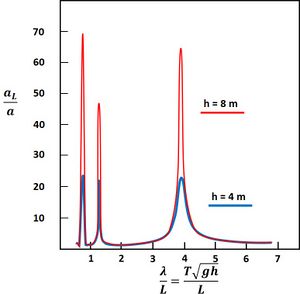
As an example, the amplification factor for a harbor of 1000 m length is shown in Fig. 1 for different depths.
Resonance damping by outward radiation
We use here the derivation of Berkhoff (1976[4]), which is similar to the original model of Miles and Munk (1961[6]). The same simplifications and approximations apply as for the previous case, with two exceptions:
- the harbor is considered frictionless ([math]F=0[/math]);
- the reflected wave radiates outward into the unbounded open sea, with the same uniform depth [math]h[/math] as the harbor.
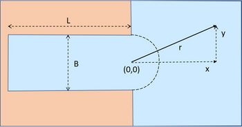
The planform is shown in Fig. 2.
The wave in the harbor [math]\hat{\zeta}_H[/math] is given by
[math]\hat{\zeta}_H(x,t)=\Re [a_L \cos(k(x+L))e^{-i \omega t}][/math].
The incident wave [math]\hat{\zeta}_I[/math] from the sea travels against the [math]x[/math] direction and is given by
[math]\hat{\zeta_{I}}(x,t)= \Re [a e^{-i(kx + \omega t)}][/math].
The width of the harbor being assumed much smaller than the length, the boundary between the harbor and the open sea can be approximated by a semicircle of radius [math]B/2[/math].
The wave [math]\hat{\zeta}_R=\zeta_R \, e^{-i \omega t}[/math] that radiates out into the sea has to satisfy the equation
[math]\Large\frac{\partial^2 \hat{\zeta}_R}{\partial t^2}\normalsize - gh \, \Big[\Large\frac{\partial^2 \hat{\zeta}_R}{\partial x^2}\normalsize + \Large\frac{\partial^2 \hat{\zeta}_R}{\partial y^2}\normalsize \Big] =0[/math].

Due to the symmetry of the outward radiation, the reflected wave only depends on the distance [math]r[/math] from the harbor entrance boundary for [math]r \gt B/2[/math]. The wave equation in polar coordinates reads
[math]r \Large\frac{\partial^2 \zeta_R}{\partial r^2}\normalsize + \Large\frac{\partial \zeta_R}{\partial r}\normalsize +k^2 r \zeta_R =0[/math].
The solution of this equation satisfying the boundary condition [math]\zeta_R \rightarrow 0[/math] for [math]r \rightarrow \infty[/math] is the Hankel function of the first kind, [math]H_0^{(1)}(kr)[/math]. The asymptotic behaviour for [math]kr \gt \gt 1[/math] of the Hankel function is [math]H_0^{(1)}=\sqrt{\large\frac{2}{ i\pi k r}\normalsize} \, e^{ikr}[/math]. Close to the harbor boundary we have [math]kr \lt \lt 1[/math], assuming that the harbor width is much smaller than the harbor length. Here the Hankel function can be approximated by [math]H_0^{(1)}(kr) \approx 1+ \large\frac{2i}{\pi}\normalsize \, (\gamma + \ln(kr/2)), \quad \gamma \approx 0.577[/math]. It should be noted that the Hankel function has a singularity at [math]r=0[/math].
The outward radiating wave is a composed by a superposition of waves radiating from different points at the harbor boundary:
[math]\zeta_R (r)= \Large\frac{1}{B}\normalsize \, \int_{-B/2}^{B/2} a_R H_0^{(1)}(kr) dy[/math].
Continuity of the surface elevation [math]\zeta[/math] and the derivative [math]d \zeta / dx[/math] at the harbor boundary implies the conditions
[math]\zeta_H=\zeta_I+ \zeta_R \quad[/math] and [math]\quad d \zeta_H /dx= d\zeta_I /dx + d \zeta_R / dx [/math].
Evaluation of these conditions yields the equations
[math]a_L \cos kL=a+2iDa_R \quad[/math] and [math] \quad -ka_L \sin kL=ika+2i \Large\frac{a_R}{B}\normalsize[/math],
where [math]D= - \Large\frac{i}{2}\normalsize + \Large\frac{1}{\pi}\normalsize (\gamma -1+\ln\Large\frac{kB}{4}\normalsize) , \quad \gamma \approx 0.577[/math].
Elimination of [math]a_R[/math] yields the amplification factor [math]R= \Large | \frac{a_L}{a} | \normalsize [/math]:
[math]\Large | \frac{a_L}{a} | \normalsize = \Large | \frac{1-ikBD}{\cos kL + kBD \sin kL} | \normalsize[/math].
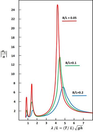
As an example, the amplification factor for a harbor of 1000 m length is shown in Fig. 3 for different widths [math]B[/math]. The effectiveness of the radiation mechanism depends primarily on the factor [math]kB=2 \pi B/ \lambda[/math], i.e. the relative width compared to the wavelength [math]\lambda[/math]. Because at resonance the wavelength is proportional to the harbor length [math]L[/math], the wave amplification in the harbor basin depends primarily on the ratio [math]B/L[/math]. The amplification factor increases for decreasing values of [math]B/L[/math].
Sloping harbor floor
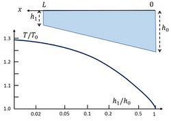
The resonance period [math]T[/math] for basins with non-uniform depth is shifted with respect to the resonance period [math]T_0[/math] for basins with uniform depth. As an example, the case of a uniformly sloping harbor floor is considered here, while assuming linear resonance dynamics. Resonance damping by friction and radiation is ignored for simplicity. This assumption is not justified in cases where the harbor is very shallow near the head. Nor can nonlinear effects related to a large amplitude-to-depth ratio be ignored in such cases, which limits the applicability of the results of the linear analysis.
In the linear case, the time ([math]t[/math]) dependence of the surface elevation [math]\hat{\zeta}(x,t)[/math] and depth averaged velocity [math]\hat{u}(x,t)[/math] can be represented by a factor [math]\exp(-i \omega t)[/math]: [math]\hat{\zeta}(x,t)=\Re [\zeta(x) \exp(-i \omega t)], \; \hat{u}(x,t)=\Re [u(x) \exp(-i \omega t)][/math]. The shallow-water equations of motion (mass balance and momentum balance, respectively) then read
[math]-i \omega \zeta + \Large\frac{d (hu)}{dx}\normalsize = 0, \quad -i \omega u + g \Large\frac{d \zeta}{dx}\normalsize = 0 , [/math]
where the depth [math]h[/math] is given by [math]h(x)=h_0+(h_1-h_0)x/L[/math]. Here we use the convention of positive increasing [math]x[/math] from the harbor entrance to the harbor head. The depth [math]h_0[/math] at the harbor entrance [math]x=0[/math] is assumed to be larger than the depth [math]h_1[/math] at the head [math]x=L[/math]. Elimination of the velocity [math]u(x)[/math] from the equations gives
[math]\omega^2 \zeta + g \Large\frac{dh}{dx} \frac{d \zeta}{dx}\normalsize + g h(x) \Large\frac{d^2 \zeta}{dx^2}\normalsize = 0 .[/math]
We introduce the variables [math]x_* = \Large\frac{h_0-h_1}{h_0} \frac{x}{L}\normalsize[/math]. The equation for [math]\zeta[/math] then becomes
[math]\zeta (x_*) \, – \, p^{-2} \Large\frac{d \zeta}{dx_*}\normalsize + p^{-2} (1-x_*) \Large\frac{d^2 \zeta}{dx_*^2}\normalsize =0 , \quad p = \Large\frac{\omega L}{\sqrt{g h_0}}\frac{h_0}{h_0-h_1}\normalsize = \Large\frac{\pi}{2}\frac{T_0}{T}\frac{h_0}{h_0-h_1}\normalsize, \quad T_0=\Large\frac{4 L}{\sqrt{g h_0}}\normalsize.[/math]

The solution of this equation is
[math]\zeta (x_*) = c_1 J_0 (2p \sqrt{1-x_*}) + c_2 Y_0 (2p \sqrt{1-x_*}) , [/math]
where [math]J_0, \; Y_0[/math] are the Bessel functions of zero order of the first and second kind respectively. The integration constants [math]c_1, \, c_2[/math] are determined from the boundary conditions
[math]\zeta (x_*=0) = a , \quad u(x_*=\Large\frac{h_0-h_1}{h_0}\normalsize) =0 [/math].
The second condition is equivalent to [math]\Large \frac{d \zeta}{dx_*}\normalsize (x_*=\Large\frac{h_0-h_1}{h_0}\normalsize) = p \sqrt{\large\frac{h_0}{h_1}\normalsize} \Big[c_1 J_1 (2p \sqrt{h_1/h_0}) + c_2 Y_1 (2p \sqrt{h_1/h_0}) \Big] = 0 [/math].
Resonance will occur if [math]c_1=\infty[/math] or [math]c_2 = \infty[/math].
From the boundary conditions and the resonance condition it follows that
[math]c_1^{-1} \propto c_2^{-1} \propto J_0(2p) \, Y_1 (2p\sqrt{h_1/h_0}) – Y_0(2p) \, J_1(2p\sqrt{h_1/h_0}) = 0 .[/math]
The periods [math]T[/math] for which resonance occurs can be derived by determining the values of [math]p[/math] satisfying this expression for given values of [math]h_1/h_0[/math]. The corresponding curve [math]T/T_0[/math] is shown in Fig. 4 as a function of [math]h_1/h_0[/math], where [math]T_0[/math] is the resonance period for a basin with uniform depth [math]h_0[/math]. Only the largest resonance period, which usually yields the largest amplification, is shown.
Related articles
References
- ↑ 1.0 1.1 Rabinovich, A.B. 2009. Seiches and harbor oscillations. In: Handbook of Coastal and Ocean Engineering (Ed. Y.C. Kim). World Scientific Publ., Singapore, pp. 193-236
- ↑ 2.0 2.1 De Jong, M.P.C. 2004. Origin and prediction of seiches in Rotterdam harbour basins. PhD thesis Delft University.
- ↑ Prandle, D. 1974. The use of wave resonators for harbour protection. The Dock Harbour Authority 1974, pp. 279–280
- ↑ 4.0 4.1 4.2 Berkhof, J.C.W. 1976. Mathematical models for simple linear water waves, refraction and diffraction. PhD Thesis Delft University
- ↑ Lee, J.J. and Xing, X. 2009. Computer Modeling for Harbor Planning and Design. In: Handbook of Coastal and Ocean Engineering (Ed. Y.C. Kim). World Scientific Publ., Singapore, pp. 695-722
- ↑ Miles, J. and Munk, W. 1961. The harbor paradox. J. Waterways Harbor Division, ASCE 87: 111–130
Please note that others may also have edited the contents of this article.
|

