Difference between revisions of "Wave energy converters in coastal structures"
(→Environmental impact) |
Dronkers J (talk | contribs) |
||
| (77 intermediate revisions by 3 users not shown) | |||
| Line 1: | Line 1: | ||
| − | {{ | + | |
| + | |||
| + | {{Review | ||
| + | |name=Job Dronkers|AuthorID=120| | ||
| + | }} | ||
| + | |||
| + | |||
| + | |||
| + | |||
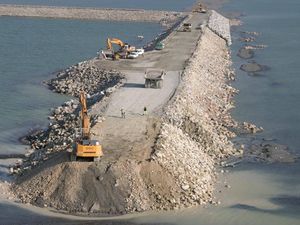
| + | [[Image:Construction_of_a_coastal_structure.jpg|thumb|right|300px|Fig 1: A coastal structure under construction.]] | ||
| + | For a general introduction to wave energy conversion methods the reader is referred to the article [[Wave energy converters]]. | ||
== Introduction == | == Introduction == | ||
| − | |||
| − | |||
| − | |||
| − | |||
| − | |||
| − | |||
| − | |||
| − | |||
| − | |||
| − | |||
| − | |||
| − | |||
| − | |||
| − | |||
| − | |||
| − | + | Coastal defence works along European coasts are composed of very diverse structures. Many coastal structures are ageing and facing problems of stability, sustainability and erosion. Moreover, climate change and especially sea level rise represent a new danger for them. [[Sea dikes|Coastal dykes]] in Europe will be exposed to [[waves]] with [[Wave height|heights]] that are greater than the dykes were designed to withstand. This will be the case, in particular, for all the structures built in shallow water where the depth imposes the maximal amplitude because of wave breaking. | |
| − | |||
| − | |||
| − | |||
| − | |||
| − | |||
| − | |||
| − | |||
| − | |||
| − | |||
| − | + | These structures need therefore to be modernized and adapted to [[climate change]]. Adaptation of dikes may also be required for other reasons, for example when navigation channels are dredged in response to the increase of maritime traffic and size of container carriers. | |
| − | |||
| − | |||
| − | |||
| − | |||
| − | |||
| − | |||
| − | |||
| − | |||
| − | |||
| − | |||
| − | |||
| − | |||
| − | |||
| − | |||
| − | |||
| − | |||
| − | |||
| − | |||
| − | |||
| − | |||
| − | |||
| − | |||
| − | + | This necessary adaptation will be costly but will provide an opportunity to integrate converters of wave energy in the new maritime structures along the coasts and in particular in harbours. This practice will contribute to the reduction of the greenhouse effect. For example, produced energy can be directly used for the energy consumption in harbour areas and will reduce the carbon footprint of harbours by feeding the docked ships with green energy. Nowadays these ships use their motors to produce electricity power on board even if they are docked. Integration of [[wave energy converters]] '''(WEC)''' in harbour structures will give substance to the new concept of 'zero-emission harbours'. | |
| − | + | As described in the article [[Wave energy converters]], current wave energy converters are not competitive on costs with other methods of energy production, such as wind turbines. Costs are currently an important bottleneck for the large-scale exploitation of wave energy. A substantial part of the costs are related to the physical structures in which wave energy converters are placed; this holds in particular for wave energy conversion by means of an oscillating water column or by means of [[wave overtopping]]. Combination of these methods of wave energy conversion with coastal structures, such as breakwaters or bulkheads, can therefore yield major cost savings. Coastal structures are generally not located where wave intensity is highest, but the resulting lower energy output is expected to be more than offset by the lower costs in most cases. | |
| − | |||
| − | |||
| − | |||
| − | |||
| − | |||
| − | |||
| − | |||
| − | |||
| − | |||
| − | |||
| − | |||
| − | |||
| − | |||
| − | |||
| − | |||
| − | |||
| − | |||
| − | |||
| − | |||
| − | |||
| − | |||
| − | |||
| − | |||
| − | |||
| − | |||
| − | |||
| − | |||
| − | |||
| − | |||
| − | |||
| − | |||
| − | |||
| − | |||
== Technologies == | == Technologies == | ||
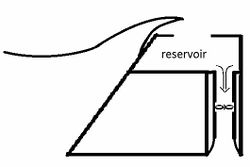
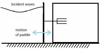
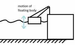
| − | According to the International Energy Agency (IEA), more than hundred systems of wave energy conversion are | + | According to the [http://www.iea.org/ International Energy Agency (IEA)], more than hundred systems of [[Wave energy converters|wave energy conversion]] are under development in the world. Among them, many can be integrated in coastal structures. Evaluations based on objective criteria are necessary in order to sort these systems and to determine the most promising solutions. The most commonly used systems can be classified according to the 4 types schematically illustrated in Fig. 2 <ref name=AL>Aderinto, T. and Li, H. 2018. Ocean Wave Energy Converters: Status and Challenges. Energies 11, 1250; doi:10.3390/en11051250</ref>, see also [[Wave energy converters]]. |
| − | < | + | |
Criteria are in particular: | Criteria are in particular: | ||
# the converter efficiency : the aim is to estimate the energy produced by the converter. The efficiency gives an estimate of the number of kWh that is produced by the machine but not the cost. | # the converter efficiency : the aim is to estimate the energy produced by the converter. The efficiency gives an estimate of the number of kWh that is produced by the machine but not the cost. | ||
| − | # the converter | + | # the converter durability : the capacity of the converter to survive in extreme conditions. The durability requirement provides an estimate of the cost considering that extreme conditions determine the costs more than proportionally compared to average conditions. |
| − | + | ||
| − | |||
| − | {| style ="margin-left: 1em | + | {| style="margin-left: 1em; margin-left:auto; margin-right:auto; width:650px; text-align:center; font-size:100%" |
|Valign="top"| [[Image:Overtopping_with_low-head_hydraulic_turbine.jpg|250px]] | |Valign="top"| [[Image:Overtopping_with_low-head_hydraulic_turbine.jpg|250px]] | ||
|Valign="top" Colspan="2"|[[Image:Submerged_oscillating_bodies_with_hydraulic_motor%2C_hydraulic_turbine%2C_linear_electrical_generator.jpg|350px]] | |Valign="top" Colspan="2"|[[Image:Submerged_oscillating_bodies_with_hydraulic_motor%2C_hydraulic_turbine%2C_linear_electrical_generator.jpg|350px]] | ||
|- | |- | ||
| − | |Valign="top"| Overtopping with low-head | + | |Valign="top"| <small>Overtopping devices (OD) with low-head hydro-turbine.</small> |
| − | |Valign="top" Colspan="2"|Submerged oscillating bodies with hydraulic motor, | + | |Valign="top" Colspan="2"|<small>Submerged oscillating bodies (SOB) with hydraulic motor, hydraulic turbine, linear electrical generator.</small> |
|- | |- | ||
|Valign="top"|[[Image:Floating oscillating bodies with hydraulic motor, hydraulic turbine.jpg|250px]] | |Valign="top"|[[Image:Floating oscillating bodies with hydraulic motor, hydraulic turbine.jpg|250px]] | ||
| Line 113: | Line 43: | ||
|[[Image:Oscillating water column with water turbine 2.jpg|180px]] | |[[Image:Oscillating water column with water turbine 2.jpg|180px]] | ||
|- | |- | ||
| − | |Valign="top"| | + | |Valign="top"| <small> Point absorbers (heaving buoys, PA) with hydraulic motor, hydraulic turbine, linear electrical generator.</small> |
| − | |Valign="top" colspan="2"|Oscillating water column with | + | |Valign="top" colspan="2"|<small>Oscillating water column (OWC) with air turbine.</small> |
|- | |- | ||
| − | |colspan ="3"| | + | | colspan ="3" |Fig 2. Schematic representation of the major different methods of wave energy conversion.<p> |
|} | |} | ||
| + | |||
| + | == Civil engineering and environmental impact== | ||
<p> | <p> | ||
| − | + | Energy conversion is only a secondary function of the coastal structure. The primary function of the coastal structure is still [[Shore protection, coast protection and sea defence methods|protection]]. It is necessary to verify whether integration of the wave energy converter (WEC) modifies performance criteria of [[Wave overtopping|overtopping]] and stability and to assess the consequences for the construction cost. | |
| − | + | ||
| − | + | Integration of a WEC in coastal structures will always be easier for a new structure than for an existing one. In the latter case, it requires some knowledge of the existing coastal structures. Solutions differ according to sea state but also to type of structures (rubble mound breakwater, caisson breakwaters with typically vertical sides). Which type of WEC is most appropriate depends on the type of coastal structure. | |
| − | + | ||
| − | + | Wave absorption will change hydrodynamics along the structure. Sand deposit can occur if the seabed in front of the structure is mobile. Change of hydrodynamics can also influence upon local ecosystems. These are aspects that must be taken into account when choosing the location of a structure for wave energy conversion. | |
| − | + | ||
| − | |||
| − | |||
| − | |||
| − | |||
| − | |||
| − | |||
| − | |||
| − | |||
| − | |||
| − | |||
| − | |||
| − | |||
| − | |||
| − | |||
| − | |||
| − | |||
| − | |||
| − | |||
| − | |||
| − | |||
| − | |||
| − | |||
| − | |||
| − | |||
| − | |||
| − | |||
| − | |||
| − | |||
| − | |||
| − | + | {| style ="margin-left: 1em" style="margin:0 auto; width:700px; text-align:center; font-size:100%" | |
| − | |||
| − | |||
| − | |||
| − | |||
| − | |||
| − | |||
| − | |||
| − | {| style ="margin-left: 1em | ||
|[[Image:Oscillating water column configuration 1.jpg|325px]] | |[[Image:Oscillating water column configuration 1.jpg|325px]] | ||
|[[Image:Oscillating water column configuration 2.jpg|325px]] | |[[Image:Oscillating water column configuration 2.jpg|325px]] | ||
| Line 170: | Line 65: | ||
|[[Image:Oscillating water column configuration 4.jpg|325px]] | |[[Image:Oscillating water column configuration 4.jpg|325px]] | ||
|- | |- | ||
| − | |colspan ="2"| | + | |colspan ="2"| Fig 3. Several designs of breakwaters with integrated OWC (Oscillating water column) converters (by Wavegen – Voith Hydro). |
|} | |} | ||
| − | + | ||
| − | + | ||
| − | + | ||
| − | + | ||
| − | + | {|style="float:right; margin-left: 1em; text-align:center; font-size:100%" | |
| − | |||
| − | |||
| − | |||
| − | |||
| − | {| | ||
|[[Image:Finistere area and locations of the six sites.jpg|250px]] | |[[Image:Finistere area and locations of the six sites.jpg|250px]] | ||
|- | |- | ||
| − | | | + | |Fig 4. Finistere area and locations of<br> the six sites (google map). |
|} | |} | ||
| − | == | + | |
| − | + | == Wave energy site selection Finistere area == | |
| − | + | ||
| − | + | The Finistère in the far west of the Brittany Peninsula is a promising area for wave energy, as it is highly exposed to ocean waves and receives the greatest influx of wave energy along the French coasts (Fig. 4). This area with a very rugged coast is also home to many commercial harbors, fishing harbors and marinas. The area produces a small part of its energy consumption and electricity power plants are situated far away. There is therefore a great interest in local production of renewable energy. This issue is of particular concern to the islands. The production of electricity by wave energy will have seasonal variations. Wave energy flux is indeed larger in winter than in summer. The consumption has peaks in winter due to heating of buildings but the consumption in summer is also strong due to the arrival of tourists. | |
| − | Six sites | + | |
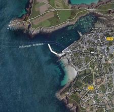
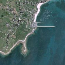
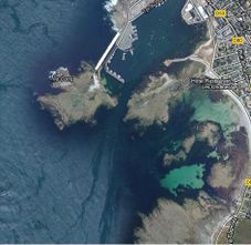
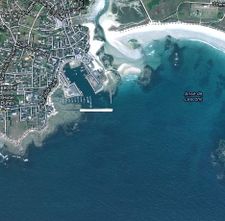
| − | + | Six sites were selected (see Fig. 5) for a preliminary study of wave energy flux and capacity of integration of wave energy converters in coastal structures. The wave energy flux was expected to be in the range of 1 – 10 kW/m. The length of each [[Application of breakwaters|breakwater]] exceeds 200 meters. The wave power along each structure is therefore estimated between 200 kW and 2 MW. Note that there exist much longer coastal structures like for example Cherbourg (France) with a length of 6 kilometres. | |
| − | + | <br style="clear:both;"/> | |
| − | {| style ="margin-left: 1em | + | |
| + | {| style ="margin-left:1em; text-align:center; font-size:100%; width:700px; margin:0 auto" | ||
|[[Image:Satelite_picture_Roskof.jpg|219px]] | |[[Image:Satelite_picture_Roskof.jpg|219px]] | ||
|[[Image:Satelite_picture_Molene.jpg|225px]] | |[[Image:Satelite_picture_Molene.jpg|225px]] | ||
|[[Image:Satelite_picture_Le_conquet.jpg|225px]] | |[[Image:Satelite_picture_Le_conquet.jpg|225px]] | ||
|- | |- | ||
| − | |(1) Roscoff (300 meters) | + | |<small>(1) Roscoff (300 meters) </small> |
| − | |(2) Molène (200 meters) | + | |<small> (2) Molène (200 meters) </small> |
| − | |(3) Le Conquet(200 meters) | + | |<small> (3) Le Conquet (200 meters) </small> |
|- | |- | ||
|[[Image:Satelite_picture_Esquibien.jpg|220px]] | |[[Image:Satelite_picture_Esquibien.jpg|220px]] | ||
| Line 207: | Line 98: | ||
|[[Image:Satelite_picture_Lesconil.jpg|225px]] | |[[Image:Satelite_picture_Lesconil.jpg|225px]] | ||
|- | |- | ||
| − | |(4) Esquibien (300 meters) | + | |<small> (4) Esquibien (300 meters) </small> |
| − | |(5) Saint-Guénolé (200 meters) | + | |<small> (5) Saint-Guénolé (200 meters) </small> |
| − | |(6) Lesconil (200 meters) | + | |<small> (6) Lesconil (200 meters) </small> |
|- | |- | ||
| − | |colspan ="3"| | + | |colspan ="3"| Fig.5. Finistere area, the six coastal structures and their length (google map). |
|} | |} | ||
| + | |||
| + | |||
| + | The wave energy flux at a structure depends on local parameters: bottom depth that fronts the structure toe, the presence of capes, the direction of waves and the orientation of the coastal structure. Fig. 6 shows the statistics of wave height and direction measured by a wave buoy located at the Pierres Noires Lighthouse. These measurements show that structures well-oriented to western waves should be chosen in priority. Peaks of consumption occur often with low temperatures in winter coming with winds from East- North-East directions. Structures well-oriented to eastern waves could therefore be also interesting even if the mean production is weak. | ||
| + | |||
| + | |||
| + | {| style ="margin-left: 1em; margin:0 auto; width: 700px; text-align:center; font-size:100%" | ||
| + | |[[Image:Waves measures at the Pierres Noires Lighthouse 1.jpg|225px]] | ||
| + | |[[Image:Waves measures at the Pierres Noires Lighthouse 2.jpg|435px]] | ||
| + | |- | ||
| + | |colspan ="2"| Fig 6: Wave measurements at the Pierres Noires Lighthouse (O=Ouest=West). | ||
| + | |} | ||
| + | |||
| + | |||
| + | |||
| + | Prototypes of an OWC device have been installed in coastal structures in Norway, Portugal, Iceland, Italy, Spain, Japan, etc. <ref name=AL/>. One example is discussed below. | ||
| + | |||
| + | ==Wave energy converters integrated in a breakwater== | ||
| + | Fixed structures near the shore are more practical and convenient because ease of installation, operation, and maintenance leads to lower costs. In addition, power transmission facilities for such devices are easier to install compared to devices located in the deep offshore areas. The main disadvantage in these low depth regions is that the wave possesses less power due to wave breaking<ref name=AL/>. | ||
| + | |||
| + | ===Oscillating water column wave converter=== | ||
| + | [[File:REWEC3Calabria.jpg|thumb|left|450px|Fig. 7. REWEC3 prototype off the beach of Reggio Calabria (Italy). From <ref>Filianoti, P. and Camporeale, S.M. 2009. In field measurements on a small-scale OCZ device. Proceedings of the 8th European Wave and Tidal Energy Conference, Uppsala, Sweden, 2009</ref>.]] | ||
| + | |||
| + | The region of Calabria in the south of Italy is, like the Finistère in France, dependent on other regions for energy supply and therefore interested in opportunities for sustainable local energy production. | ||
| + | <ref>Dominguez-Ramos, A., Triantafyllidis, C.P., Samsatli, S., Nilay, S. and Irabien, A. 2016. Renewable electricity integration at a regional level: Cantabria case study. Computer Aided Chemical Engineering 38: 211-216</ref>. Wave energy is one of the options, which was studied by the Università degli Studi "Mediterranea" di Reggio Calabria. They developed the so-called '''REWEC''' that consists of an oscillating water column (OWC) wave converter integrated in a multi-caisson breakwater (Fig.7). The dimensions of the OWC chambers in each caisson are chosen such that the natural frequency of the oscillating water column is close to the frequency of the highest incoming waves; in this way the most efficient wave energy conversion is achieved (Boccotti, 2003<ref>Boccotti, P. 2003. On a new wave energy absorber. Ocean Engineering 30: 1191–1200</ref>). A full-scale wave energy converter of the REWEC3 type has been completed in 2015 as part of the new breakwater of the harbour of Civitavecchia (about 60 km north-west of Rome). The installed power of about 2.6 MW is divided over 136 independent OWC chambers, each equipped with a Wells turbo-generator set of about 18-20 kW. The additional costs for building a REWEC3 caisson compared to a traditional breakwater caisson were estimated to be approximately 5-7%. | ||
| + | |||
| + | [[File:REWEC3Civitavecchia.jpg|thumb|900px|center|Fig. 8. REWEC3 OCW breakwater wave converter. Panel a: Location (in red) in the harbour of Civitavecchia. Panel b: Cross-section of REWEC3; the OCW inlet is 6-8 m below the LW line. Panel c: View of the construction emerging above the sea surface. From: Felice Arena, presentation "Resonant Wave Energy Converters | ||
| + | REWEC3: primi prototipi nei porti di Civitavecchia e di Salerno" at Naples Shipping Week, 2016.]] | ||
| + | |||
| + | |||
| + | When vertical seawalls (e.g., bulkhead or caisson constructions) are used as harbor quays, it can be necessary to reduce the reflection of incoming waves on the quay. To this end, openings are often made in the quay wall, with behind a space in which wave energy is dissipated. This type of construction can be adapted to incorporate an OWC wave energy conversion system. The energy supplied by the OWC is then a by-product of the wave damping effect of the quay wall, which can be realized with modest additional costs. A numerical simulation study shows that a built-in OWC system can achieve at least the same reduction of reflected waves as conventional methods, by appropriately selecting the dimensions of the OWC chamber<ref>Simonetti, I. and Capietti, L. 2021. Hydraulic performance of oscillating water column structures as anti-reflection devices to reduce harbour agitation. Coastal Engineering 165: 103837</ref>. In this study, the best reduction (wave reflection coefficient of approximately 0.15) was achieved when the length of the OWC chamber (i.e. depth behind the quay wall) was approximately 15% of the average incoming wavelengths. Geometric optimization of the OWC device is required as the wave energy conversion performance depends on the geometrical proportions. Important optimization parameters are the relative size of the top aperture and the relative inlet length, and to a lesser extent the relative inlet height<ref>Deng, Z., Wang, C., Wang, P., Higuera, P. and Wang, R. 2019. Hydrodynamic performance of an offshore-stationary OWC device with a horizontal bottom plate: Experimental and numerical study. Energy 187, 115941</ref>. | ||
| + | |||
| + | |||
| + | |||
| + | ===[[Wave overtopping|Overtopping]] breakwater for energy conversion=== | ||
| + | [[File:OBRECprototype.jpg|thumb|left|300px|Fig. 9. The OBREC protoype installed in a breakwater of Naples Harbour. It has two drain openings for collecting overtopping waves; the openings are at different levels for design testing. Picture from Vicinanza et al. (2017<ref name=V17>Vicinanza, D., Contestabile, P. and Di Lauro, E. 2017. Overtopping Breakwater for Wave Energy Conversion: Status and Perspective. Proceedings of the 12th European Wave and Tidal Energy Conference 27th Aug -1st Sept 2017, Cork, Ireland, paper 1194</ref>).]] | ||
| + | |||
| + | Another design for combining wave energy extraction with wave damping at harbor entrances uses the energy of [[Wave overtopping|overtopping]] waves. Drain openings in the sloping berm of a breakwater collect the water of overtopping waves, that is then discharged through low-head turbines; these turbines are coupled to generators that convert the rotary motion into electrical energy. This type of integrated WEC is called '''OBREC''' (Overtopping BReakwater for Energy Conversion). A prototype of the OBREC has been installed in 2015 along 6 m of the San Vincenzo rubble mound breakwater in Naples Harbour in Italy (Fig. 9). The coastal area where the OBREC has been installed has a depth of 25 m and a low estimated mean yearly wave power of 2.5 kW/m<ref name=V17>Vicinanza, D., Contestabile, P. and Di Lauro, E. 2017. Overtopping Breakwater for Wave Energy Conversion: Status and Perspective. Proceedings of the 12th European Wave and Tidal Energy Conference 27th Aug -1st Sept 2017, Cork, Ireland, paper 1194</ref>. The structure is multifunctional, aiming to protect the harbour and to produce energy at the same time. A case study intended to assess the feasibility of an OBREC type wave energy converter on the west coast of Australia suggested that OBREC gives its best performance (and high economic confidence) in a poor and mild wave climate. It appeared that very energetic waves lead to a saturated condition of the reservoir, for which a large amount of overtopping was reflected as outgoing<ref>Contestabile, P., Di Lauro, E., Buccino, M. and Vicinanza, D. 2017. Economic Assessment of Overtopping Breakwater for Energy Conversion (OBREC): A Case Study in Western Australia. Sustainability 9, 51; doi:10.3390/su9010051</ref>. Another conclusion is that breakwater modifications aimed at increasing the efficiency of wave energy extraction are generally not profitable if additional costs are incurred. However, numerical models show that optimizing the design of the OBREC can be cost effective. This study shows that installing a sloped ramp towards the overtopping drain openings in combination with a crownwall increases the stability of the breakwater structure by taking more advantage of the downward pressure of the captured overtopping waves<ref>Di Lauro, E., Maza, M., Lara, J.L., Losada, I.J., Contestabile, P. and Vicinanza, D. 2020. Advantages of an innovative vertical breakwater with an overtopping wave energy converter. Coastal Engineering 159, 103713</ref>. | ||
| + | <br clear=all/> | ||
| + | [[File:SSG-WEC.jpg|thumb|right|300px|Fig. 10. The SeaWave Slot-Cone Generator (SSG) has several levels where the energy of overtopping waves is collected.]] | ||
| + | |||
| + | |||
| + | A more sophisticated design of the OBREC called "SeaWave Slot-Cone Generator (SSG)" was developed at Aalborg University (Denmark)<ref>Vicinanza, D., Margheritini, L., Kofoed, J.P. and Buccino, M. 2012.The SSG Wave Energy Converter: Performance, Status and Recent Developments. Energies 5: 193-226</ref>. It collects seawater by wave overtopping over several reservoirs placed above each other, resulting in high hydraulic efficiency. The reservoir capacity smooths out the irregularity of incoming waves, providing a regular electricity output to the grid. Additionally, with the turbine shaft and the gates controlling the water flow, SSG is built as a robust concrete structure with few moving parts in the mechanical system, making it a low maintenance, durable system. No prototype has yet been built. | ||
| + | <br clear=all/> | ||
| + | |||
| + | == Conclusion == | ||
| + | <p> | ||
| + | Wave energy converters (WEC) in coastal structures can be considered as a land renewable energy. The expected energy can be compared with the energy of land wind farms but not with offshore wind farms whose number and power are much larger. As a land system, the maintenance will be easy. Except the energy production, systems integrated in harbour infrastructures have other advantages such as : | ||
| + | * a “zero emission” port | ||
| + | * industrial tourism | ||
| + | * test of WEC for future offshore installations. | ||
| + | |||
| + | |||
| + | == Acknowledgement == | ||
<p> | <p> | ||
| + | This work was carried out as part of the national project EMACOP funded by the French Ministry of Ecology, Sustainable Development and Energy. | ||
| + | |||
| + | |||
| + | == See also == | ||
| + | * [[Wave energy converters]] | ||
| + | * [[Shallow-water wave theory]] | ||
| + | * [[Hard coastal protection structures]] | ||
| + | |||
| + | |||
==References== | ==References== | ||
<references/> | <references/> | ||
| − | + | ||
| − | + | ||
| − | |||
<div align="center"> | <div align="center"> | ||
{| style="border:1px solid #abd5f5; background:#f1f5fc; margin:0em 0em 0em 0em;" | {| style="border:1px solid #abd5f5; background:#f1f5fc; margin:0em 0em 0em 0em;" | ||
| − | |<center>The main author of this article is [http://www.coastalwiki.org/index.php?option=com_imis&module=person&Itemid=17&persid=11176 Sergent, Philippe]<br><small>With contributions by: François Bouttes, Bertrand Michard, Alain Clément, Aurélien Babarit, Virginie Baudry, Michel Benoit and Giovanni Mattarolo</small></center> | + | |<center>The main author of this article is [http://www.coastalwiki.org/index.php?option=com_imis&module=person&Itemid=17&persid=11176 Sergent, Philippe]<br><small>With contributions by: François Bouttes, Bertrand Michard, Emmanuel Cosquer, Alain Clément, <br> Aurélien Babarit, Virginie Baudry, Michel Benoit and Giovanni Mattarolo</small></center> |
---- | ---- | ||
| Line 229: | Line 181: | ||
| − | + | [[Category:Hard structures]] | |
| − | [[Category: | + | [[Category:Hydrodynamics]] |
| + | [[Category:Marine energy]] | ||
Latest revision as of 14:51, 25 February 2023
For a general introduction to wave energy conversion methods the reader is referred to the article Wave energy converters.
Contents
Introduction
Coastal defence works along European coasts are composed of very diverse structures. Many coastal structures are ageing and facing problems of stability, sustainability and erosion. Moreover, climate change and especially sea level rise represent a new danger for them. Coastal dykes in Europe will be exposed to waves with heights that are greater than the dykes were designed to withstand. This will be the case, in particular, for all the structures built in shallow water where the depth imposes the maximal amplitude because of wave breaking.
These structures need therefore to be modernized and adapted to climate change. Adaptation of dikes may also be required for other reasons, for example when navigation channels are dredged in response to the increase of maritime traffic and size of container carriers.
This necessary adaptation will be costly but will provide an opportunity to integrate converters of wave energy in the new maritime structures along the coasts and in particular in harbours. This practice will contribute to the reduction of the greenhouse effect. For example, produced energy can be directly used for the energy consumption in harbour areas and will reduce the carbon footprint of harbours by feeding the docked ships with green energy. Nowadays these ships use their motors to produce electricity power on board even if they are docked. Integration of wave energy converters (WEC) in harbour structures will give substance to the new concept of 'zero-emission harbours'.
As described in the article Wave energy converters, current wave energy converters are not competitive on costs with other methods of energy production, such as wind turbines. Costs are currently an important bottleneck for the large-scale exploitation of wave energy. A substantial part of the costs are related to the physical structures in which wave energy converters are placed; this holds in particular for wave energy conversion by means of an oscillating water column or by means of wave overtopping. Combination of these methods of wave energy conversion with coastal structures, such as breakwaters or bulkheads, can therefore yield major cost savings. Coastal structures are generally not located where wave intensity is highest, but the resulting lower energy output is expected to be more than offset by the lower costs in most cases.
Technologies
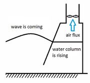
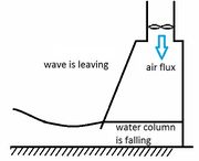
According to the International Energy Agency (IEA), more than hundred systems of wave energy conversion are under development in the world. Among them, many can be integrated in coastal structures. Evaluations based on objective criteria are necessary in order to sort these systems and to determine the most promising solutions. The most commonly used systems can be classified according to the 4 types schematically illustrated in Fig. 2 [1], see also Wave energy converters.
Criteria are in particular:
- the converter efficiency : the aim is to estimate the energy produced by the converter. The efficiency gives an estimate of the number of kWh that is produced by the machine but not the cost.
- the converter durability : the capacity of the converter to survive in extreme conditions. The durability requirement provides an estimate of the cost considering that extreme conditions determine the costs more than proportionally compared to average conditions.
Civil engineering and environmental impact
Energy conversion is only a secondary function of the coastal structure. The primary function of the coastal structure is still protection. It is necessary to verify whether integration of the wave energy converter (WEC) modifies performance criteria of overtopping and stability and to assess the consequences for the construction cost. Integration of a WEC in coastal structures will always be easier for a new structure than for an existing one. In the latter case, it requires some knowledge of the existing coastal structures. Solutions differ according to sea state but also to type of structures (rubble mound breakwater, caisson breakwaters with typically vertical sides). Which type of WEC is most appropriate depends on the type of coastal structure. Wave absorption will change hydrodynamics along the structure. Sand deposit can occur if the seabed in front of the structure is mobile. Change of hydrodynamics can also influence upon local ecosystems. These are aspects that must be taken into account when choosing the location of a structure for wave energy conversion.

|

|

|

|
| Fig 3. Several designs of breakwaters with integrated OWC (Oscillating water column) converters (by Wavegen – Voith Hydro). | |
|
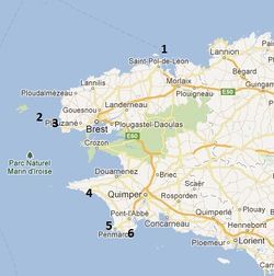
| Fig 4. Finistere area and locations of the six sites (google map). |
Wave energy site selection Finistere area
The Finistère in the far west of the Brittany Peninsula is a promising area for wave energy, as it is highly exposed to ocean waves and receives the greatest influx of wave energy along the French coasts (Fig. 4). This area with a very rugged coast is also home to many commercial harbors, fishing harbors and marinas. The area produces a small part of its energy consumption and electricity power plants are situated far away. There is therefore a great interest in local production of renewable energy. This issue is of particular concern to the islands. The production of electricity by wave energy will have seasonal variations. Wave energy flux is indeed larger in winter than in summer. The consumption has peaks in winter due to heating of buildings but the consumption in summer is also strong due to the arrival of tourists.
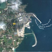
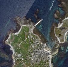
Six sites were selected (see Fig. 5) for a preliminary study of wave energy flux and capacity of integration of wave energy converters in coastal structures. The wave energy flux was expected to be in the range of 1 – 10 kW/m. The length of each breakwater exceeds 200 meters. The wave power along each structure is therefore estimated between 200 kW and 2 MW. Note that there exist much longer coastal structures like for example Cherbourg (France) with a length of 6 kilometres.
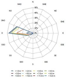
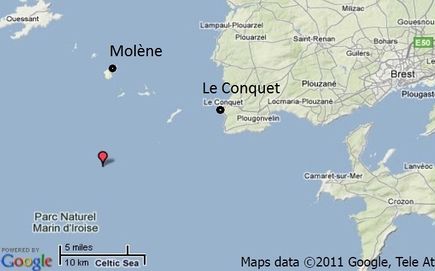
The wave energy flux at a structure depends on local parameters: bottom depth that fronts the structure toe, the presence of capes, the direction of waves and the orientation of the coastal structure. Fig. 6 shows the statistics of wave height and direction measured by a wave buoy located at the Pierres Noires Lighthouse. These measurements show that structures well-oriented to western waves should be chosen in priority. Peaks of consumption occur often with low temperatures in winter coming with winds from East- North-East directions. Structures well-oriented to eastern waves could therefore be also interesting even if the mean production is weak.
|
|
| Fig 6: Wave measurements at the Pierres Noires Lighthouse (O=Ouest=West). | |
Prototypes of an OWC device have been installed in coastal structures in Norway, Portugal, Iceland, Italy, Spain, Japan, etc. [1]. One example is discussed below.
Wave energy converters integrated in a breakwater
Fixed structures near the shore are more practical and convenient because ease of installation, operation, and maintenance leads to lower costs. In addition, power transmission facilities for such devices are easier to install compared to devices located in the deep offshore areas. The main disadvantage in these low depth regions is that the wave possesses less power due to wave breaking[1].
Oscillating water column wave converter

The region of Calabria in the south of Italy is, like the Finistère in France, dependent on other regions for energy supply and therefore interested in opportunities for sustainable local energy production. [3]. Wave energy is one of the options, which was studied by the Università degli Studi "Mediterranea" di Reggio Calabria. They developed the so-called REWEC that consists of an oscillating water column (OWC) wave converter integrated in a multi-caisson breakwater (Fig.7). The dimensions of the OWC chambers in each caisson are chosen such that the natural frequency of the oscillating water column is close to the frequency of the highest incoming waves; in this way the most efficient wave energy conversion is achieved (Boccotti, 2003[4]). A full-scale wave energy converter of the REWEC3 type has been completed in 2015 as part of the new breakwater of the harbour of Civitavecchia (about 60 km north-west of Rome). The installed power of about 2.6 MW is divided over 136 independent OWC chambers, each equipped with a Wells turbo-generator set of about 18-20 kW. The additional costs for building a REWEC3 caisson compared to a traditional breakwater caisson were estimated to be approximately 5-7%.

When vertical seawalls (e.g., bulkhead or caisson constructions) are used as harbor quays, it can be necessary to reduce the reflection of incoming waves on the quay. To this end, openings are often made in the quay wall, with behind a space in which wave energy is dissipated. This type of construction can be adapted to incorporate an OWC wave energy conversion system. The energy supplied by the OWC is then a by-product of the wave damping effect of the quay wall, which can be realized with modest additional costs. A numerical simulation study shows that a built-in OWC system can achieve at least the same reduction of reflected waves as conventional methods, by appropriately selecting the dimensions of the OWC chamber[5]. In this study, the best reduction (wave reflection coefficient of approximately 0.15) was achieved when the length of the OWC chamber (i.e. depth behind the quay wall) was approximately 15% of the average incoming wavelengths. Geometric optimization of the OWC device is required as the wave energy conversion performance depends on the geometrical proportions. Important optimization parameters are the relative size of the top aperture and the relative inlet length, and to a lesser extent the relative inlet height[6].
Overtopping breakwater for energy conversion
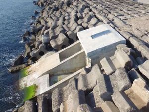
Another design for combining wave energy extraction with wave damping at harbor entrances uses the energy of overtopping waves. Drain openings in the sloping berm of a breakwater collect the water of overtopping waves, that is then discharged through low-head turbines; these turbines are coupled to generators that convert the rotary motion into electrical energy. This type of integrated WEC is called OBREC (Overtopping BReakwater for Energy Conversion). A prototype of the OBREC has been installed in 2015 along 6 m of the San Vincenzo rubble mound breakwater in Naples Harbour in Italy (Fig. 9). The coastal area where the OBREC has been installed has a depth of 25 m and a low estimated mean yearly wave power of 2.5 kW/m[7]. The structure is multifunctional, aiming to protect the harbour and to produce energy at the same time. A case study intended to assess the feasibility of an OBREC type wave energy converter on the west coast of Australia suggested that OBREC gives its best performance (and high economic confidence) in a poor and mild wave climate. It appeared that very energetic waves lead to a saturated condition of the reservoir, for which a large amount of overtopping was reflected as outgoing[8]. Another conclusion is that breakwater modifications aimed at increasing the efficiency of wave energy extraction are generally not profitable if additional costs are incurred. However, numerical models show that optimizing the design of the OBREC can be cost effective. This study shows that installing a sloped ramp towards the overtopping drain openings in combination with a crownwall increases the stability of the breakwater structure by taking more advantage of the downward pressure of the captured overtopping waves[9].
A more sophisticated design of the OBREC called "SeaWave Slot-Cone Generator (SSG)" was developed at Aalborg University (Denmark)[10]. It collects seawater by wave overtopping over several reservoirs placed above each other, resulting in high hydraulic efficiency. The reservoir capacity smooths out the irregularity of incoming waves, providing a regular electricity output to the grid. Additionally, with the turbine shaft and the gates controlling the water flow, SSG is built as a robust concrete structure with few moving parts in the mechanical system, making it a low maintenance, durable system. No prototype has yet been built.
Conclusion
Wave energy converters (WEC) in coastal structures can be considered as a land renewable energy. The expected energy can be compared with the energy of land wind farms but not with offshore wind farms whose number and power are much larger. As a land system, the maintenance will be easy. Except the energy production, systems integrated in harbour infrastructures have other advantages such as :
- a “zero emission” port
- industrial tourism
- test of WEC for future offshore installations.
Acknowledgement
This work was carried out as part of the national project EMACOP funded by the French Ministry of Ecology, Sustainable Development and Energy.
See also
References
- ↑ 1.0 1.1 1.2 Aderinto, T. and Li, H. 2018. Ocean Wave Energy Converters: Status and Challenges. Energies 11, 1250; doi:10.3390/en11051250
- ↑ Filianoti, P. and Camporeale, S.M. 2009. In field measurements on a small-scale OCZ device. Proceedings of the 8th European Wave and Tidal Energy Conference, Uppsala, Sweden, 2009
- ↑ Dominguez-Ramos, A., Triantafyllidis, C.P., Samsatli, S., Nilay, S. and Irabien, A. 2016. Renewable electricity integration at a regional level: Cantabria case study. Computer Aided Chemical Engineering 38: 211-216
- ↑ Boccotti, P. 2003. On a new wave energy absorber. Ocean Engineering 30: 1191–1200
- ↑ Simonetti, I. and Capietti, L. 2021. Hydraulic performance of oscillating water column structures as anti-reflection devices to reduce harbour agitation. Coastal Engineering 165: 103837
- ↑ Deng, Z., Wang, C., Wang, P., Higuera, P. and Wang, R. 2019. Hydrodynamic performance of an offshore-stationary OWC device with a horizontal bottom plate: Experimental and numerical study. Energy 187, 115941
- ↑ 7.0 7.1 Vicinanza, D., Contestabile, P. and Di Lauro, E. 2017. Overtopping Breakwater for Wave Energy Conversion: Status and Perspective. Proceedings of the 12th European Wave and Tidal Energy Conference 27th Aug -1st Sept 2017, Cork, Ireland, paper 1194
- ↑ Contestabile, P., Di Lauro, E., Buccino, M. and Vicinanza, D. 2017. Economic Assessment of Overtopping Breakwater for Energy Conversion (OBREC): A Case Study in Western Australia. Sustainability 9, 51; doi:10.3390/su9010051
- ↑ Di Lauro, E., Maza, M., Lara, J.L., Losada, I.J., Contestabile, P. and Vicinanza, D. 2020. Advantages of an innovative vertical breakwater with an overtopping wave energy converter. Coastal Engineering 159, 103713
- ↑ Vicinanza, D., Margheritini, L., Kofoed, J.P. and Buccino, M. 2012.The SSG Wave Energy Converter: Performance, Status and Recent Developments. Energies 5: 193-226
With contributions by: François Bouttes, Bertrand Michard, Emmanuel Cosquer, Alain Clément, Aurélien Babarit, Virginie Baudry, Michel Benoit and Giovanni Mattarolo
|
