Coriolis and tidal motion in shelf seas
Tides are generated in the ocean in response to the gravitational attraction of moon and sun. Ocean tides generate tidal motion in the shelf seas. Tidal motion in the shelf seas differs from the ocean tide due to the much smaller water depth and the presence of land boundaries. In this article some characteristics of tidal motion in shelf seas are discussed, complementing the more general introduction in the article Ocean and shelf tides. Although the discussion is restricted to simple geometries – uniform depth and straight coastlines – the general characteristics are similar to tidal motion in shelf seas with more complex geometries.
Tidal waves in wide basins are strongly influenced by earth's rotation (Coriolis acceleration). Tidal waves turn around so-called amphidromic points, where the vertical motion is almost nil. At some distance from the basin boundaries the tidal current vector describes an ellipse during the tidal period.
Contents
Introduction
The tide on the continental shelf mainly co-oscillates with the tide in the adjacent ocean. The tide-generating force due to the moon's and sun's gravitational pull hardly plays a role at the scale of the continental shelf sea. Rather, much of the ocean's tidal energy is dissipated on the continental shelf, as explained in more detail in the article Ocean and shelf tides. Due to their role as sink of tidal energy, one might assume that shelf seas have lower tides than the ocean. However, the opposite is generally the case. Several factors contribute to strengthening the tide when it propagates from the ocean to the continental shelf. This is qualitatively related to the following processes:
- When propagating from the ocean onto the continental shelf, the tidal wave experiences a strong decrease in depth, often a factor 10 to 50. The tide propagation speed is approximately given by [math]c \sim \sqrt{gh}[/math], where [math]g[/math] is the gravitational acceleration and [math]h[/math] the water depth. The energy flux associated with tide propagation is approximately given by [math]F = E c \sim ½ g \rho a^2\sqrt{gh}[/math], where [math]\rho[/math] is the seawater density and [math]a[/math] the tidal amplitude. The reduction of the propagation speed causes a decrease of the energy flux as the tide enters the continental shelf. Although Coriolis acceleration diverts most of the tidal energy along the continental shelf break, part of it accumulates on the shelf. This accumulation of tidal energy results in an increase of the tidal amplitude. The increase in tidal amplitude (approximately as [math]a \propto h^{-1/4}[/math]) restores continuity of the tidal energy flux over the continental shelf.
- Many regions of the continental shelf have a funnel-type topography. When propagating into a gradually narrowing region, continuity of the tidal energy flux across the basin implies an increase in the tidal amplitude that compensates for the decrease in basin width [math]b[/math] (approximately as [math]a \propto b^{-1/2}[/math]). Extreme examples are the English Channel, Bristol channel, Baie du Mont-Saint-Michel, Bay of Fundy.
- The reduction in tide propagation speed implies a corresponding reduction in tidal wavelength, compared to the wavelength in the ocean. The distance the tidal wave travels to the coastal boundary where the tidal wave is reflected can thus be close to a quarter tidal wave length. In such cases resonance will occur, unless the tidal wave is substantially damped by friction. The tide will then have maximum amplitude at the coastal boundary and a node near the continental margin, where the amplitude is several or even many times smaller than at the coastal boundary. Because the tidal amplitude at the continental margin is imposed by the ocean tide, the tide at the coastal boundary can be much larger than the ocean tide. This applies, for example, for the examples cited above.
Tidal motion in shelf seas is more complex than suggested by the qualitative arguments given above. This is not only due to the important influence of Coriolis acceleration, the influence of wind and density stratification, but especially due to the intricate topography of the shelf sea floor and boundaries. The presence of estuaries at the land boundaries is another complicating factor that cannot be ignored. They represent an important sink of tidal energy related to their shallowness and intertidal zones. The tidal wave can be strongly distorted in estuaries, as described in the article Tidal asymmetry and tidal basin morphodynamics, and sometimes evolve into a tidal bore. The simulation of tidal motion in shelf seas and adjacent estuaries therefore requires detailed numerical modelling, for which several software packages are currently available.
For simple geometries, the equations governing tidal motion can be simplified so that analytical solutions can be obtained. This article focuses on such simple analytical models. They do not provide an accurate description of tidal motion that can be used for application in practice. However, they provide important understanding of the general characteristics of tidal motion in shelf seas which is essential for interpreting the results of complex numerical models.
Assumptions
We will restrict the discussion to hypothetical situations where the following assumptions approximately hold:
- a shelf sea of uniform depth and uniform density;
- a single (semi-diurnal) tidal component with radial frequency [math]\omega[/math] ;
- tidal motion driven by the ocean tide at the shelf boundary;
- tide-generating forces of moon and sun are negligible for the selected domain;
- latitudinal variation of the Coriolis parameter [math]f[/math] can be neglected;
- frictionless tidal flow;
- tidal amplitude much smaller than water depth;
- current velocities much smaller than tidal wave celerity [math]c[/math].
Tidal equations
With the above assumptions, the depth-averaged tidal equations (momentum balance and mass balance) including coriolis acceleration [math]f=2\Omega \sin \phi[/math], can be written as:
[math] \Large \frac{\partial u}{\partial t} \normalsize - f v + g \Large \frac{\partial \eta}{\partial x} \normalsize =0 , \qquad (1)[/math]
[math] \Large \frac{\partial v}{\partial t} \normalsize + f u + g \Large \frac{\partial \eta}{\partial y} \normalsize =0 , \qquad (2)[/math]
[math] \Large \frac{\partial \eta}{\partial t} \normalsize + h \; ( \Large \frac{\partial u}{\partial x} + \Large \frac{\partial v}{\partial y} \normalsize ) =0 . \qquad (3)[/math]
The following conventions are used:
- [math]u,v[/math] are the depth-averaged tidal current velocities in [math]x,y[/math]-directions, respectively;
- [math]\eta[/math] is the tide level;
- [math]h[/math] is the average depth;
- [math]\Omega[/math] is the radial frequency of earth's rotation;
- [math]\phi[/math] is the latitude expressed in radians (positive for the northern hemisphere, negative for the southern hemisphere).
The current velocities [math]u,v[/math] can be eliminated from the tidal equations (1-3); this gives the wave equation
[math]\Large \frac{\partial^2 \eta }{\partial t^2} \normalsize + f^2 \eta = gh \; (\Large \frac{\partial^2 \eta }{\partial x^2} + \frac{\partial^2 \eta }{\partial y^2} \normalsize ) . \qquad (4)[/math]
Dispersion relation
The solution of equation (4) for a free propagating tidal wave (no boundaries) has the form
[math] \eta(x,y,t) = A \cos(kx+my-\omega t) e^{\large -\kappa x - \mu y \normalsize}. \qquad (5)[/math]
The propagation direction is given by the vector [math]\vec k = (k,m)[/math], and the phase speed is given by [math]c=\omega / \sqrt{k^2+m^2} .[/math] Substitution of this solution yields the dispersion relation
[math] gh(k^2+m^2-\kappa^2-\mu^2+2i(k \kappa +m \mu))=\omega^2-f^2 . \qquad (6)[/math]
By choosing the [math]x[/math]-axis along the propagation direction (i.e. [math]m=0, \; k=\omega / c[/math]), the dispersion relation requires [math]\kappa =0[/math] and
[math]gh(k^2-\mu^2)=\omega^2-f^2 . \qquad (7)[/math]
For the tidal wave solution the corresponding velocity components are given by
[math]u = \Large \frac{k \omega - \mu f }{\omega^2-f^2} \normalsize \, g \eta , \; v = \Large \frac{k f - \mu \omega}{\omega^2-f^2} \normalsize \, g \eta \tan(kx-\omega t). \qquad (8)[/math]
At [math]x=0[/math] the velocity components are
[math]u = U (1 - \Large \frac{\mu f c}{\omega^2} \normalsize) \cos \omega t, \; v = - U \Large \frac{f -\mu c}{\omega} \normalsize \sin \omega t , \; U = c \Large \frac{A/h} {1 -(\mu c / \omega)^2} \normalsize e^{\large -\mu y \normalsize }. \qquad (9)[/math]
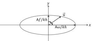
For [math]\mu c \lt f \lt \omega ,[/math] the current vector ([math]u,v[/math]) rotates anti-cyclonically around an ellipse; for [math]\mu=0[/math] the demi-axes are ([math]A \omega / kh, A|f|/kh[/math]), see figure 1.
Kelvin wave
A particular solution for a tidal wave propagating in positive [math]x[/math]-direction along the coast corresponds to
[math]\mu = f/c , \; c=\sqrt{gh} . \qquad (10)[/math]
For this solution, which is called Kelvin wave, we have [math] v=0[/math] (tidal velocity parallel to the shoreline) and
[math] \eta(x,y,t)= A e^{\large-fy/c \normalsize } \cos(kx-\omega t) ,\; u= (Ac/h) e^{\large -fy/c \normalsize } \cos(kx-\omega t). \qquad (11)[/math]
The Kelvin wave is a reasonable approximation for tidal waves in the vicinity of a straight coastline [math]y=y_0[/math], where [math]v \approx 0[/math].
The Kelvin wave is largest near the coastline and exponentially damped further away; it propagates along the coast with the coastline at the right hand in the northern hemisphere ([math]f,y\gt y_0[/math]) and with the coastline at the left hand in the southern hemisphere ([math]f,y\lt y_0[/math]). For a Kelvin wave propagating in negative [math]x[/math]-direction along the coast (northern hemisphere) [math]\mu = -f/c [/math].
Amphidromic point
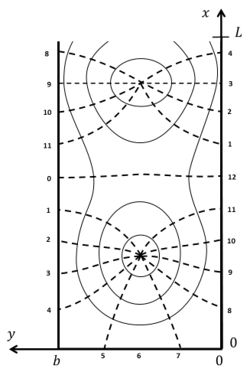
A tidal wave propagating in a rectangular basin of length [math]L[/math] can be described by the sum of two Kelvin waves. In the northern hemisphere (figure 2) we have an incoming wave propagating in negative [math]x[/math]-direction along the left boundary [math]y=b[/math] and a reflected wave propagating in positive [math]x[/math]-direction along the right boundary [math]y=0[/math],
[math]\eta = (a/2) \left[e^{\large f(y- ½ b)/c \normalsize }\cos(kx+\omega t) + e^{\large -f(y- ½ b)/c \normalsize } \cos(kx-\omega t) \right] , \qquad (12)[/math]
[math]u = (ca/2h) \left[- e^{\large f(y- ½ b)/c \normalsize }\cos(kx+\omega t) + e^{\large -f(y- ½ b)/c \normalsize } \cos(kx-\omega t) \right] . \qquad (13)[/math]
The closed landward boundary is at [math]x=0[/math] and the open seaward boundary at [math]x=L[/math]. At [math]x = ½ \pi/k, y = ½ b[/math] the vertical wave motion is zero; this is the so-called amphidromic point. In long basins another amphidromic point exists at [math]x = (3/2) (\pi/k), y = ½ b[/math]. In long wide basins the tidal wave composed of incoming and reflected Kelvin waves turns around amphidromic points, see figure 2.
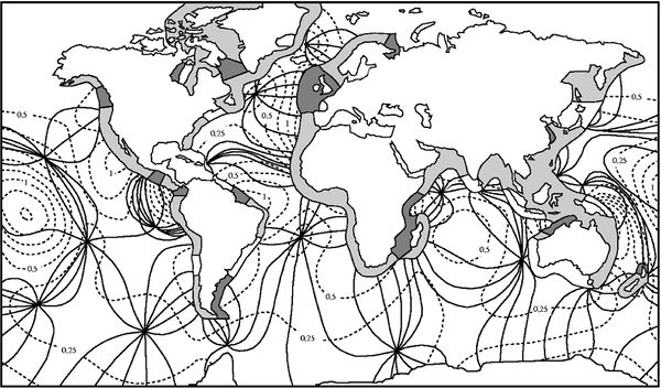
In the ocean, the semidiurnal lunar tidal wave turns around amphidromic points, see figure 3. This illustrates that ocean tides have the characteristics of a system of Kelvin waves.
Boundary conditions
We consider a tidal basin with a closed end at [math]x=0[/math]. The width [math]b[/math] is much smaller than the tidal wavelength [math]2 \pi \sqrt{gh}/\omega[/math], which is smaller than the basin length [math]L[/math]. Because Kelvin waves are not a full solution of the tidal equations, the condition [math]u=0[/math] at the closed end is satisfied only for [math]y=b/2[/math]. Other wave solutions have to be taken into account near the closed end of the basin. These are standing waves, sometimes called Poincaré waves or Sverdrup waves. They are periodic in the lateral coordinate [math]y[/math] in order to satisfy the condition [math]v=0[/math] at the lateral basin boundaries [math]y=(0,b) [/math],
[math]v = \sum_{n=1}^{n=\infty} v_n, \quad v_n = V_n e^{\large - p_n x \normalsize } \sin (\large \frac{n \pi y }{b} \normalsize) \cos(\omega t) . \qquad (14)[/math]
According to this equation, the spatial and temporal dependence of the tidal elevation and tidal velocities is represented by a series of functions
[math]\eta, \; u, \; v \sim \exp(p_n x) \exp(i \large\frac{n \pi y}{b}\normalsize) \exp(i \omega t) . \qquad (15)[/math]
Substitution in equation (4) gives the dispersion relation
[math]p_n^2 =(\Large \frac{n\pi}{b})^2- \frac{\omega^2-f^2}{gh} \normalsize . \qquad (16)[/math]
In basins which are much narrower than the tidal wavelength, [math]n \pi /b \gt \gt \omega / \sqrt{gh}[/math], the exponents [math]p_n[/math] are real positive numbers, [math]p_n \approx n \pi /b[/math]. The Poincaré waves are significant only near the end of the basin and strongly damped elsewhere. The contribution of the Poincaré waves to the velocity [math]u[/math] can be derived by substitution of the expressions (15) in the equations (1, 2).
The coefficients [math]V_n[/math] are determined from the condition
[math]u_K(0,y,t)+u_P(0,y,t)=0[/math]
at the closed boundary [math]x=0[/math]. The subscripts [math]K,P[/math] indicate the Kelvin and Poincaré wave contributions, respectively. A first order approximate solution is
[math]u_K= V_1 e^{\large - p_1 x \normalsize } \cos (\large \frac{ \pi y }{b} \normalsize) \cos(\omega t) , \qquad V_1=-(A/h)bf/\pi .[/math]
The Poincaré wave solution for satisfying the seaward boundary condition (the ocean tide at [math]x=L[/math]) can be found in a similar way. An analytical solution for the problem of tidal motion in a rectangular basin was first given by G.I. Taylor in 1921 [1], as shown in figure 2.
Influence of friction
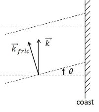
Inclusion of friction influences the tidal wave in several important ways[2][3]. Analytical expressions can be derived if the tidal equations are linearised, see Appendices A and B. Here we summarize some major consequences of the inclusion of friction terms in the tidal equations.
(1) The crests of Kelvin waves are not perpendicular to the coastline, but are rotated in cyclonic direction with respect to the propagation direction, see figure 4. The wave propagation direction is away from the coast.
(2) The amphidromic points are not situated on the centreline of rectangular semi-enclosed basins, but they are shifted in cyclonic direction relative to the propagation direction of the incoming tidal wave, see figure 5.
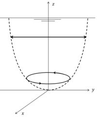
(3) The current velocity vector rotates in cyclonic direction with increasing distance from the water surface[4][5], see figure 6. This can be shown by decomposing the tidal current into two circular rotating components, one component rotating in cyclonic direction and the other component in anticyclonic direction. If the magnitude of the two components is the same, the tidal current is rectilinear. Frictional damping depends on the rotation sense. The anticyclonic component is more strongly damped with increasing depth than the cyclonic component; the latter therefore generally dominates near the bottom.
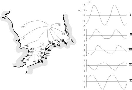
(4) In shallow coastal zones, with significant tide compared to the depth, the Kelvin wave propagates faster at high tide than at low tide. The tidal wave therefore becomes increasingly distorted in the propagation direction; tidal rise becomes faster than fall (see for an explanation: Tidal asymmetry and tidal basin morphodynamics). This is illustrated in figure 5 for the tidal wave propagating along the Dutch coast. Fast tidal rise causes stronger flood currents than ebb currents in adjacent tidal lagoons and estuaries. This tidal asymmetry stimulates sediment import. It can result in silting up of lagoons and in the formation of turbidity maxima in estuaries.
Appendix A Linear friction
In the case of linear friction the depth-averaged tidal equations (1-3) take the form
[math] \Large \frac{\partial u}{\partial t} \normalsize - f v + g \Large \frac{\partial \eta}{\partial x} \normalsize = -R \Large\frac{u}{h}\normalsize , \qquad (A1)[/math]
[math] \Large \frac{\partial v}{\partial t} \normalsize + f u + g \Large \frac{\partial \eta}{\partial y} \normalsize = -R \Large\frac{v}{h}\normalsize , \qquad (A2)[/math]
[math] \Large \frac{\partial \eta}{\partial t} \normalsize + h \; ( \Large \frac{\partial u}{\partial x} + \Large \frac{\partial v}{\partial y} \normalsize ) =0 . \qquad (A3)[/math]
where [math]R[/math] is the linear friction coefficient. This coefficient can be approximated by [math]R \approx c_D h U[/math], where [math]c_D \sim 0.002-0.004[/math] is the so-called drag coefficient (see Bed roughness and friction factors in estuaries), [math]h[/math] is the water depth and [math]U[/math] is an order of magnitude estimate of the mean tidal current velocity.
The solution for the Kelvin wave along the coast where [math]v=0[/math] is now given by an expression of the form
[math] \eta(x,y,t)= A e^{ - \large\frac{fy}{c_1} - \mu x\normalsize } \cos(kx + \large\frac{fy}{c_2}\normalsize - \omega t) . \qquad (A4) [/math]
The coefficients [math]c_1, c_2, k, \mu[/math] can be determined by substitution in the equations (A1-A3), giving
[math] c_1=\Large\frac{\omega}{k}\normalsize \big(1+r^2\big)^{1/2} , \quad c_2=\Large\frac{\omega}{\mu}\normalsize \big(1+r^2 \big)^{1/2}, \quad k=\Large\frac{\omega}{\sqrt{2gh}}\normalsize \Big(1+\big(1+r^2\big)^{1/2} \Big)^{1/2} , \quad \mu=\Large\frac{\omega}{\sqrt{2gh}}\normalsize \Big(-1+\big(1+r^2\big)^{1/2} \Big)^{1/2} , \quad r=\Large\frac{R}{\omega h}\normalsize .\qquad (A5)[/math]
Equation (A4) shows that the propagation direction now makes a small angle [math]\theta[/math] with the [math]y[/math]-axis given by [math]\theta=\Large\frac{f}{c_2 k}\normalsize[/math], see Fig. 4.
For the semi-enclosed basin considered in Fig. 2 the tidal elevation [math]\eta(x,y,t)[/math] of Eq. (12) is replaced by
[math]\eta = (a/2) \Big[e^{-\large\frac{f}{c_1}(y - ½b) - \mu x \normalsize }\cos(kx + \large\frac{f}{c_2}\normalsize (y - ½b) - \omega t) + e^{\large \frac{f}{c_1}(y - ½b) + \mu x \normalsize }\cos(k x + \large\frac{f}{c_2}\normalsize (y - ½b) - \omega t) \Big] . \qquad (A6)[/math]
The amphidromic point is situated at [math]x=\Large\frac{\pi}{2k}[/math]. At this latitude the tidal elevation (A6) is given by
[math]\eta = a \sinh \Big(\Large\frac{f}{c_1}\normalsize (y - ½b) + \Large\frac{\pi \mu}{2k}\normalsize \Big) \; \sin \Big(\Large\frac{f}{c_2}\normalsize (y - ½b) - \omega t \Big) [/math].
The longitude coordinate of the amphidromic point is thus given by [math]y = ½ b - \Large\frac{\pi \mu c_1}{2 k f} [/math].This means that friction displaces the amphidromic point cyclonically relative to the incoming wave (to the left in the northern Hemispere).
Appendix B Tidal boundary layer
Here an analytical expression for the vertical velocity profile is derived, based on a few simplifying assumptions following the derivation of Prandle (1982[4]). Independent linear equations are obtained when the velocity is decomposed in two components that rotate with the tide due to the Coriolis acceleration. One component rotates in cyclonic direction and a second component in anticyclonic direction. The tidal equations can be approximated by linear expressions when momentum advection can be ignored and when the eddy viscosity can be assumed constant over the vertical and the tidal cycle. This latter assumption is a strong simplification, even in the case of vertically well-mixed conditions and in the absence of density effects. The tidal elevation [math]\eta(x,y,t)[/math] is assumed to be known; an approximate analytic expression can be derived by the methods indicated above.
The tidal equations for the velocity components [math]u(x,y,z,t), v(x,y,z,t)[/math] are written as
[math] \Large \frac{\partial u}{\partial t} \normalsize - f v + g \Large \frac{\partial \eta}{\partial x} \normalsize =N\Large\frac{\partial^2 u}{\partial z^2}\normalsize , \qquad (B1)[/math]
[math] \Large \frac{\partial v}{\partial t} \normalsize + f u + g \Large \frac{\partial \eta}{\partial y} \normalsize = N\Large\frac{\partial^2 v}{\partial z^2}\normalsize , \qquad (B2)[/math] ,
where [math]N[/math] is the eddy viscosity. An order of magnitude estimate is given by [math]N \sim 0.5 h_l u*[/math], where [math]u_* = c_D U [/math] is the turbulent shear velocity, [math]c_D \sim 0.002-0.004[/math] is the bottom drag coefficient (see Bed roughness and friction factors in estuaries), [math]h_l[/math] is the depth of the logarithmic layer and [math]U[/math] is an order of magnitude estimate of the mean tidal current velocity. An empirical estimate of the depth of the logarithmic layer [math]h_l[/math] is given by [math]h_l \sim 0.04 u_* / \omega \approx 30 \sqrt{c_D} U \;[/math][6]. A typical value of [math]h_l[/math] is of the order of 5-20 m.
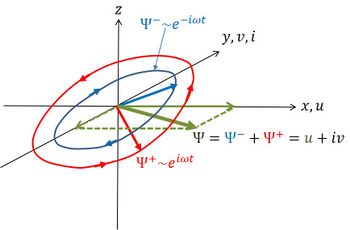
A right-handed reference frame is chosen as shown in Fig. B1, with the [math]z[/math]-axis pointing upwards from the water surface ([math]z=0[/math]). The top of the logarithmic bottom boundary layer is at [math]z=-h[/math]. The depth [math]h[/math] is much larger than the tidal amplitude and assumed constant. The tidal velocities are assumed to satisfy zero-flux boundary conditions at the water surface and a slip condition at the interface with the boundary layer,
[math]\Large\frac{\partial u}{\partial z}\normalsize=0 , \quad \Large\frac{\partial v}{\partial z}\normalsize=0 , \quad z=0 , \qquad (B3)[/math]
[math]\Large\frac{\partial u}{\partial z}\normalsize=su , \quad \Large\frac{\partial v}{\partial z}\normalsize=sv , \quad z=-h , \qquad (B4)[/math]
where [math]s[/math] is a slip coefficient of order [math]s \sim 1/h[/math].
Now consider the complex velocity vector [math]\Psi=u+iv[/math], where [math]u[/math] is aligned with the [math]x[/math]-axis and [math]iv[/math] with the positive (negative) [math]y[/math]-axis for positive (negative) values of [math]v[/math]. Multiplying Eq. (B2) by [math]i[/math] and adding to Eq. (B1) gives the tidal equation for [math]\Psi[/math],
[math] \Large \frac{\partial \Psi}{\partial t} \normalsize + if \Psi + \Phi=N\Large\frac{\partial^2 \Psi}{\partial z^2}\normalsize , \qquad (B5)[/math]
with [math]\Phi =g \Big(\Large \frac{\partial \eta}{\partial x} \normalsize + i \, \Large \frac{\partial \eta}{\partial y} \normalsize \Big) . \qquad (B6)[/math].
The boundary conditions are
[math]\Large\frac{\partial \Psi}{\partial z}\normalsize=0 , \quad z=0 ; \qquad \Large\frac{\partial \Psi}{\partial z}\normalsize=s\Psi , \quad z=-h . \qquad (B7)[/math]
The complex velocity [math]\Psi[/math] is decomposed in a cyclonically rotating vector (superscript +) and an anticyclonically rotating vector (superscript -),
[math]\Psi = \Psi^+(x,y,z) e^{i\omega t} + \Psi^-(x,y,z) e^{-i\omega t} . \qquad (B8)[/math].
Similarly, the complex water level gradient (6) is decomposed as
[math]\Phi = - i (\omega + f) \Phi^+(x,y) e^{i\omega t} + i (\omega -f) \Phi^-(x,y) e^{-i\omega t} . \qquad (B9)[/math].
Substitution in Eq. (B5) gives
[math]\Psi^{\pm} – (\kappa^{\pm})^{-2} \Large\frac{\partial^2 \Psi}{\partial z^2}\normalsize = \Phi^{\pm} , \quad \kappa^{\pm}=(1 \pm i) k^{\pm} , \quad k^{\pm} = \sqrt{\Large\frac{\omega \pm f}{2N}\normalsize} , \qquad (B10)[/math]
where it has been assumed that [math]\omega \gt f[/math] (the usual case except at high latitude).
The solution of Eq. (B10) is
[math]\Psi = e^{i \omega t} \Big(\Phi^+ + A_1^+ e^{\kappa^+ z} + A_2^+ e^{-\kappa^+ z}\Big) + e^{- i \omega t} \Big(\Phi^- + A_1^- e^{\kappa^- z} + A_2^- e^{-\kappa^- z} \Big) . \qquad (B11)[/math].
Substitution in the boundary conditions (B7) at [math]z=0[/math] and [math]z=-h[/math] gives
[math]\Psi^{\pm} = \Phi^{\pm} \Big(1 - \Large\frac{s}{s+\kappa^{\pm} \tanh \kappa^{\pm} h}\frac{\cosh \kappa^{\pm} z}{\cosh \kappa^{\pm} h}\normalsize \Big) . \qquad (12)[/math]
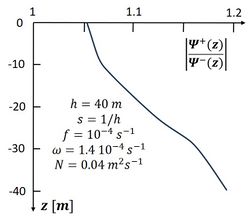
By evaluating this expression for various realistic values of [math]\kappa^{\pm}, h, s, z[/math] it appears that the anticyclonic component [math]\Psi^-[/math] is more strongly reduced by friction than the cyclonic component [math]\Psi^+[/math], as [math]k^+ \gt k^-[/math], see Fig. B2. The reason for the stronger reduction of the anticyclonic component follows from the slip condition (B4). According to the expression (B11) and the formulas for [math]\kappa^{\pm}[/math], the anticyclonic component experiences a greater momentum loss to the boundary layer than the cyclonic component. A physical interpretation is that the cyclonic rotation component assists the Coriolis force in balancing bottom friction, while the anticyclonic rotation component has the opposite effect[7].
Symbols
| Variable | Description | Variable | Description | Variable | Description |
|---|---|---|---|---|---|
| [math]a[/math] | tidal amplitude | [math]L[/math] | basin length | [math]z[/math] | vertical coordinate |
| [math]b[/math] | basin width | [math]N[/math] | eddy viscosity | [math]\eta[/math] | tidal surface elevation |
| [math]c[/math] | tide propagation velocity | [math]r=\large\frac{R}{h \omega}\normalsize[/math] | scaled linear friction coefficient | [math]k^{\pm}[/math] [math]\kappa^{\pm}=(1\pm i)k^{\pm}[/math] |
inverse boundary layer depth for cyclonic/anticyclonic tidal wave components; complex exponent |
| [math]c_D[/math] | bottom drag coefficient | [math]R[/math] | linear friction coefficient | [math]\mu[/math] | tide attenuation coefficient |
| [math]E[/math] | tidal energy | [math]s[/math] | bottom slip coefficient | [math]\rho[/math] | seawater density |
| [math]f[/math] | Coriolis coefficient | [math]t[/math] | time | [math]\rho \, \Phi[/math] | complex pressure gradient |
| [math]g=9.8 \, m^2s^{-1}[/math] | gravitational acceleration | [math]u[/math] | velocity in [math]x-[/math]direction | [math]\Psi=u+iv[/math] | complex tidal current velocity |
| [math]h[/math] | mean water depth | [math]v[/math] | velocity in [math]y-[/math]direction | [math]\Psi^{\pm}[/math] | cyclonic/anticyclonic components of [math]\Psi[/math] |
| [math]\vec{k}=(k,m)[/math] | wave number vector | [math]x[/math] | longitudinal coordinate | [math]\omega[/math] | radial tidal frequency |
| [math]k[/math] | wave number [math]x-[/math]direction | [math]y[/math] | lateral coordinate | [math]\Omega=7.29 \, 10^{-5} \, s^{-1}[/math] | radial earth rotation frequency |
Related articles
References
- ↑ Taylor, G.I. (1922) Tidal oscillations in gulfs and rectangular basins. Proc. London Math. Soc. 20:148–181
- ↑ Pedlosky, J. (1979) Geophysical Fluid Dynamics. Springer Verlag, 624 pp.
- ↑ Rienecker, M.M. and Teubner, M.D. (1980) A note on frictional effects in Taylor’s problem. J Mar Res 38(2):183–191
- ↑ 4.0 4.1 Prandle, D. (1982) The vertical structure of tidal currents. Geophys. and Astrophys. Fluid Dynamics 22: 29-49
- ↑ Maas, L.R.M. and Van Haren, J.J.M. (1987) Observations on the vertical structure of tidal and inertial currents in the central North Sea. Journal of Marine Research. 45: 293-318
- ↑ Lueck, R.G. and Lu, Y. (1997) The logarithmic layer in a tidal channel. Continental Shelf Research 17: 1785-1801
- ↑ Werner, S.R., Beardsley, R.C., Lentz, S.J., Hebert, D.L. and Oakey, N.S. 2003. Observations and modeling of the tidal bottom boundary layer on the southern flank of Georges Bank, J. Geophys. Res. 108(C11), 8005
Please note that others may also have edited the contents of this article.
|
