Edge wave
Definition of Edge waves:
Obliquely incident waves trapped to the shore by wave refraction and reflection.
This is the common definition for Edge waves, other definitions can be discussed in the article
|
Characteristics
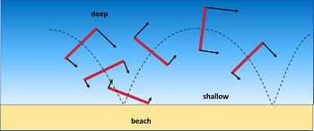
Edge waves are waves which are trapped in a coastal strip with seaward increasing depth. The wavelength is comparable with or smaller than the width of the sloping coastal strip. These longer period waves (infragravity waves) do not break on the shore, but are (partially) reflected. The reflected wave cannot escape to deep water (see the Fig. 1) and will travel along the shore as a so-called edge wave. Infragravity waves can be generated in shallow water by nonlinear interaction processes within short wave groups, see Infragravity waves. Infragravity waves can also generated by other causes, see Seiche.
Although generally true that the largest amplitude of edge waves is likely to be shoreward of the breaker line, the form of edge waves is not directly linked to the breaker line: they may decay in amplitude well within the breaking zone or may extend well beyond it. The cross-shore scale of the seaward decay is related to the alongshore wavelength.
The maximum amplitude of an edge wave occurs at the shoreline over a beach that slopes continuously seawards, with an exponential seawards decay over a linearly sloping beach. However over a barred beach the amplitude can become large over the bar crest.
Beach cusps along pocket beaches (beaches enclosed between headlands) have sometimes been associated with standing edge waves, resulting from edge wave reflection at the headlands.
Edge wave dispersion relation[1]
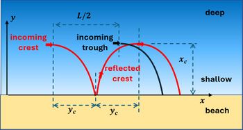
Consider a plane seabed, uniform in the alongshore [math]y[/math]-direction and with a uniform sloping depth [math]h=x \, \tan \beta[/math] in seaward [math]x[/math]-direction. The dispersion relation of edge waves can be derived from the refraction condition. This condition states that incoming and reflected waves have to annihilate where the reflected wave is refracting back (at [math]x=x_c[/math]) from seaward directed to onshore directed (see Fig. 2). Destructive interference occurs if the phase [math]k_y L/2[/math] of the incoming wave (wave trough) is equal to the phase [math]2 k_y y_c[/math] of the reflected wave (wave crest). (This condition is similar to the destructive interference of incoming and reflecting waves at the open boundary of a frictionless prismatic canal of length [math]L/4[/math].)
According to Snellius' law, the alongshore wavenumber [math]k_y = 2 \pi / L[/math] is independent of [math]x[/math]. We have [math]k_y = k \sin \alpha[/math], where [math]k[/math] is the wave number and [math]\alpha(x)[/math] the wave ray angle. The refraction condition can be written
[math]\quad y_c = L/4 = \pi/(2k_y) = \int_0^{x_c} \cot \alpha(x) \, dx .\qquad (1)[/math]
An expression of [math]\alpha(x)[/math] can be derived by assuming that the wave propagation speed can be approximated by the shallow-water formula [math]c^2=g \, h = g\, x \, \tan \beta[/math]. We have by definition [math]c=\omega/k=\omega \, \sin \alpha / k_y [/math]. Combining the two equations gives [math]\sin^2 \alpha = (k_y / \omega)^2 g \, x \, \tan \beta[/math]. Because [math]\alpha = 1[/math] at the refraction line [math]x=x_c[/math], we also have [math]1 / x_c = (k_y / \omega)^2 g \, \tan \beta[/math] and [math]\sin^2 \alpha = x / x_c[/math]. From the latter equality follows [math]dx = 2 x_c \sin \alpha \cos \alpha[/math], which can be substituted in the integral (1). We then find
[math]y_c = \pi / (2 k_y) = \int_0^{x_c} \cot \alpha \, dx = 2 x_c \int_0^{\pi/2} \cos^2 \alpha \, d \alpha = (\pi/2) x_c . \qquad (2)[/math].
Using the expression of [math]1/x_c[/math] we find the dispersion relation for the 0-mode edge wave: [math]\quad \omega^2 = g \, k_y \, \tan \beta . \qquad (3)[/math]

Appendix: Mathematical derivation
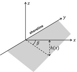
Here we derive expressions for non-dissipative short waves travelling over a sloping seabed (Fig.3). For simplicity we assume a uniform bathymetry in the alongshore direction. Edge waves are generally considered to be infragravity waves (intermediate between short breaking waves and long tidal waves), which dissipate little energy due to the thin turbulent boundary layer. The wave equations therefore assume irrotational flow, but do take into account non-hydrostatic pressure. The equations are linearized for the sake of simplicity.
The continuity equation: [math]\quad \Large\frac{\partial u }{\partial x}\normalsize + \Large\frac{\partial v}{\partial y}\normalsize + \Large\frac{\partial w}{\partial z}\normalsize =0 . \qquad (A1) [/math]
The non-hydrostatic pressure equation: [math]\quad \Large\frac{\partial w}{\partial t}\normalsize + \Large\frac{1}{\rho}\frac{\partial p}{\partial z}\normalsize = -g . \qquad (A2)[/math]
The condition at the sloping seabed ([math]z = -h(x)[/math]) : [math] \quad w = - u \Large\frac{dh}{dx}\normalsize . \qquad (A3) [/math]
Symbols (Fig. 3): [math]x=[/math] cross-shore coordinate (seaward >0), [math]y=[/math] longshore coordinate, [math]z=[/math] vertical coordinate (upward >0), [math] u, v, w[/math] are the velocities in the [math]x, y, z[/math] directions, [math]h(x)=[/math] mean depth, [math]dh/dx=\tan \beta=[/math] seabed slope, [math]\eta=[/math] wave elevation, [math]p=[/math] pressure, [math]g=[/math] gravitational acceleration, [math]\rho=[/math] seawater density.
Seabed friction is ignored. The wave motion is irrotational, and can thus be described by a velocity potential [math]\phi(x,y,z,t)[/math] ,
[math]u = \Large\frac{\partial \phi}{\partial x}\normalsize , \quad v = \Large\frac{\partial \phi}{\partial y}\normalsize , \quad w = \Large\frac{\partial \phi}{\partial z}\normalsize . \qquad (A4)[/math]
The wave equations can then be written as
Continuity equation: [math]\quad \Large\frac{\partial^2 \phi}{\partial x^2}\normalsize + \Large\frac{\partial^2 \phi}{\partial y^2}\normalsize +\Large\frac{\partial^2 \phi}{\partial z^2}\normalsize =0 . \qquad (A5)[/math]
Non-hydrostatic pressure equation: [math]\quad \Large\frac{\partial^2 \phi}{\partial z \partial t}\normalsize + \Large\frac{1}{\rho}\frac{\partial p}{\partial z}\normalsize = -g . \qquad (A6) [/math]
Seabed condition: [math]\quad \Large\frac{\partial \phi}{\partial z}\normalsize = -\tan \beta \Large\frac{\partial \phi}{\partial x}\normalsize . \qquad (A7)[/math]
The pressure is eliminated by integrating Eq. (A6) to the surface, [math]\quad \Large\frac{\partial \phi}{\partial t}\normalsize = - g \eta \quad [/math] and differentiation: [math]\quad \Large\frac{\partial^2 \phi}{\partial t^2}\normalsize = - g w = - g \Large\frac{\partial \phi}{\partial z}\normalsize \, , \; z=0 . \qquad (A8) [/math]
The solution of the linear equations Eqs. (A5, A7, A8) which is harmonic in the alongshore direction, represents an edge wave propagating along the coast with period [math]T = 2 \pi / \omega [/math] and wave number [math]k_y[/math],
[math]\phi(x,y,z,t) = e^{i \omega t + i k_y y} f(x,z) , \qquad (A9)[/math]
where [math]f(x,z)[/math] is a superposition of exponential functions. The simplest function (mode 0 edge wave or Stokes edge wave) is
[math]f_0(x,z) = a_0 e^{k_y(- x \cos \beta + z \sin \beta)} , \quad [/math] with corresponding dispersion relation [math]\quad \omega^2 = g k_y \sin \beta . \qquad (A10)[/math]
The dispersion relation of higher edge wave modes [math]f_n(x,z) [/math] is given by[1] [math]\quad \omega^2 = g k_y \sin ((2n+1) \beta) . \qquad (A11)[/math]
The corresponding wavelengths are [math]\lambda_y = \Large\frac{2 \pi}{k_y}\normalsize = \Large\frac{g T^2}{2 \pi}\normalsize \sin ((2n+1) \beta). \qquad (A12)[/math]
See also
References
Please note that others may also have edited the contents of this article.
|

