Wave transmission by low-crested breakwaters
Definition of Low-crested breakwaters:
Low-crested breakwaters are manmade wave damping structures in nearshore waters with crest level just above or just below the still water level (SWL). The latter category, also known as submerged breakwater, has a negative freeboard [math]R_c[/math].
This is the common definition for Low-crested breakwaters, other definitions can be discussed in the article
|
Definition of Transmitted wave:
The transmitted wave is the onshore propagating wave after being damped by an artificial or natural obstacle. The wave transmission coefficient [math]K_t[/math] is the ratio of the wave heights of the transmitted and incoming waves.
This is the common definition for Transmitted wave, other definitions can be discussed in the article
|
Notes
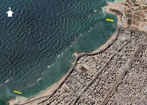
Submerged and low-crested breakwaters are specifically designed to mitigate the attack of incoming waves and thereby protect beaches against erosion. While these structures only partially reduce incoming waves, they offer several advantages over high-crested breakwaters. They do not obstruct the view of the sea and allow water circulation and flushing between the structure and the beach. These types of breakwaters are commonly utilized to protect tourist beaches (see Fig. 1). One drawback is the presence of rip currents along the extremities of the breakwater. These rip currents are driven by wave-induced water level set-up at the onshore side of the breakwater[1][2].
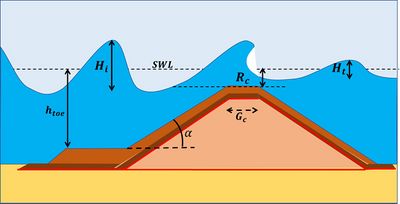
The wave transmission performance of a low-crested breakwater is expressed by means of the wave transmission coefficient [math]K_t = H_t / H_i[/math]. The transmission coefficient depends primarily on (see Fig. 2):
- the freeboard [math]R_c[/math], the distance between the breakwater crest level and the still water level (positive for emergent crest and negative for submerged crest)
- the width [math]G_c[/math] of the breakwater crest
- the spectral wave height [math]H_i[/math] of the incoming wave at the toe of the structure (approximately equal to the significant wave height, see Statistical description of wave parameters)
- The wave conditions, represented by the surf similarity parameter [math]\xi = \Large\frac{\tan \alpha}{\sqrt{H_i / L}}[/math].
Meaning of the symbols:
- [math]H_t[/math] the spectral height of the transmitted wave
- [math]L = g T_p^2 / (2 \pi)[/math] the wavelength
- [math]T_p[/math] the peak spectral wave period
- [math]\tan\alpha[/math] the slope of the structure
- [math]g[/math] the gravitational acceleration
Several empirical expressions for the wave transmission coefficient have been derived from laboratory experiments and tested in field situations. A frequently used formula, was established by D’Angremond et al. (1997[3]) for unbroken waves and for the range [math]0.075 \lt K_t \lt 0.8[/math],
[math]K_t \equiv \Large\frac{H_t}{H_i}\normalsize = c_1 \Large\frac{R_c}{H_i}\normalsize + c_2 \Big( \Large\frac{G_c}{H_i} \Big)^{c_3} \normalsize [1 - \exp(c_4 \xi)] , \qquad (1) [/math]
where [math]c_1=-0.4, \; c_2=0.8, \; c_3=-0.31, \; c_4=-0.5[/math]. For permeable breakwaters (e.g. rubble-mound breakwaters with porosity of about 0.5) the coefficient [math]c_2=0.8[/math] should be replaced by [math]c_2=0.64[/math].
Application of this formula to over 4000 available laboratory and field data shows that 62% of data falls within a confidence level of 20% and 87% of data falls within a confidence level of 50%[4].
Since it was observed that this formula overestimates the wave transmission of wide-crested breakwaters ([math]G_c / H_i \gt 10[/math]), an adjusted set of parameters for this case was proposed by Briganti et al. (2004[5]) with coefficients [math]c_1=-0.35, \; c_2=0.51, \; c_3=-0.65, \; c_4=-0.41[/math].
Noticing the weak dependence of the transmission coefficient on the wave steepness and the slope of the structure, Van Gent et al. (2023[7]) derived from a series of flume experiments the alternative formula,
[math]K_t = c_5 + c_1 \tanh \Bigg(c_4 - \Large\frac{R_c}{H_i}\normalsize +c_2 \bigg( \Large\frac{G_c}{L} \bigg)^{c_3} \normalsize \Bigg) , \qquad (2)[/math]
where [math]c_1=0.47, \; c_2=3.1, \; c_3=0.75, \; c_4=0, \; c_5=0.5 [/math] for impermeable smooth structures. For permeable structures (e.g. rubble-mound, with porosity of about 0.5) the values of the coefficients [math]c_1, c_4[/math] should be replaced by [math]c_1=0.41, \; c_4=-0.25[/math]. The formula (2) was established for a series of experiments with [math]\; -2.5\lt R_c/H_i \lt 2.5, \; 0.017 \lt G_c / L \lt 0.27, \; 0.015 \lt H_i / L \lt 0.033[/math] and trapezoidal structures with slope 1 : 2.
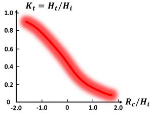
Fig. 3 gives a rough visual estimate of the transmission coefficient from laboratory data as a function of the relative freeboard.
Related articles
- Detached breakwaters
- Wave overtopping
- Stability of rubble mound breakwaters and shore revetments
- Modelling coastal hydrodynamics
References
- ↑ Burcharth, H. F., Kramer, M., Lamberti, A. and Zanuttigh, B. 2006. Structural Stability of Detached Low Crested Breakwaters. Coastal Engineering 53: 381-394
- ↑ Kim, I.H., Lee, W.D., Shin, S., Kim, J.H., Hur, D.S. and Cho, W.C. 2016. Study on Rip Current Generated by Submerged Breakwaters: Field Observation and Numerical Simulation. Journal of Coastal Research 75: 1352-1356
- ↑ d’Angremond, K., van der Meer, J.W. and de Jong, R.J. 1997. Wave Transmission at Low-Crested Structures. In Coastal Engineering 1996, ASCE, pp. 2418–2427
- ↑ 4.0 4.1 Brancasi, A., Leone, E., Francone, A., Scaravaglione, G. and Tomasicchio, G.R. 2022. On Formulae for Wave Transmission at Submerged and Low-Crested Breakwaters. J. Mar. Sci. Eng. 10, 1986
- ↑ Briganti, R., van der Meer, J., Buccino, M. and Calabrese, M. 2004. Wave Transmission Behind Low-Crested Structures. In Coastal Structures 2003, ASCE, Reston, USA, pp. 580–592
- ↑ CIRIA/CUR/CETMEF 2007. The Rock Manual. The use of rock in hydraulic engineering (2nd ed.). C683. London: CIRIA
- ↑ 7.0 7.1 van Gent, M.R.A., Buis, L., van den Bos, J.P. and Wüthrich, D. 2023. Wave transmission at submerged coastal structures and artificial reefs. Coastal Engineering 184, 104344
Please note that others may also have edited the contents of this article.
|


