Difference between revisions of "Measuring instruments for coasts"
(→Instruments for coasts) |
|||
| Line 7: | Line 7: | ||
* particle sizes and fall velocities, | * particle sizes and fall velocities, | ||
| − | are presented in Tables 1, 2 and 3 below | + | are presented in Tables 1, 2 and 3 below. The order of preference is based on the overall sampling accuracy. |
[[Image:H534figure0.jpg|thumb|700px|centre|Tables 1, 2 and 3]] | [[Image:H534figure0.jpg|thumb|700px|centre|Tables 1, 2 and 3]] | ||
Revision as of 13:28, 4 December 2007
This article is a summary of sub-section 5.3.4 of the Manual Sediment Transport Measurements in Rivers, Estuaries and Coastal Seas[1]. This article describes which instruments are available to measure different aspects of sediment transport along the coast. The article also goes into location of sampling.
Contents
Instruments for coasts
The available instruments (and accuracies involved) for measuring:
- bed load transport,
- suspended sediment concentrations and transport rates
- particle sizes and fall velocities,
are presented in Tables 1, 2 and 3 below. The order of preference is based on the overall sampling accuracy.
Field instruments to measure bed-load transport in oscillatory flow are hardly available. Katori (1983[2]) using a stand-alone mechanical trap-type sampler, performed experiments to measure the cross-shore sediment transport rate at and near the bed on a sandy beach at the Pacific Ocean coast of Japan (shallow surf zone).
Instruments available for measuring suspended sediment concentrations and transport in coastal environments are: mechanical traps (streamer traps in shallow surf zone <1 m), pump samplers, optical samplers and acoustic samplers.
Mechanical trap samplers have been used extensively in Japan, in Poland (Antsyferov et al, 1990[3]), in the USA (Kraus, 1987[4]) and in Russia (Antsyferov et al, 1990[3]). These types of instruments, which can only be used in the shallow surf zone (depths <1 m) by operators wading in the water, are simple and reliable. Simultaneous measurements in many points and stations can be performed. Kraus (1987[4]) used portable traps, consisting of long rectangular bags of polyester sieve cloth mounted on a vertical rack to measure longshore suspended load transport rates. An operator standing downcurrent attends the trap during the sampling interval (5 to 10 min), The use of the trap is restricted to surf zones with wave heights less than about 0.5 m in water depths upto l m. Antsyferov et al (1990[3]) used traps mounted on tripods placed in and outside the surf zone. The traps were replaced by divers. Typical sampling periods are ranging from 10 min to 1 day. The sediment mass collected by each trap gives an indication of the local time-averaged concentration. Determination of the trapping coefficient is problematic. Therefore, relative concentrations rather than absolute concentrations are obtained. Kana (1979[5]) used an instantaneous trap sampler in the surf zone. Many samples at the same location are required to eliminate the random fluctuations.
Pump samplers were used by many researchers to measure time-averaged sediment concentrations. These types of samplers can only be used from a pier or platform. The intake nozzles should be directed downwards.
Optical and acoustic probes are available to measure instantaneous sediment concentrations from a pier or platform or from a stand-alone tripod. Data transmission can take place by telemetry or on-line to a computer or datalogger. Calibration of the probes is required. Optical probes cannot be used in conditions with both sand and silt particles in suspension. The optical instruments are relatively sensitive to fine mud particles. Hence, the mud background concentration must be small (<50 mg/1). Otherwise, the sand concentrations cannot be measured accurately.
Acoustic probes cannot be used in plunging breaking wave conditions due to the presence of air bubbles.
Nuclear probes which have been used in Russia and in China, cannot be used in low-energy conditions where the concentrations are relatively small. The threshold concentration is of the order of 500 mg/1.
On-line and stand-alone sampling
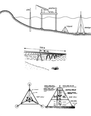
Suspended sediment transport measurements in conditions with combined current and wave conditions cannot be performed from moored or sailing survey ships. Two options are possible (see Figure 1):
- on-line sampling from piers connected to shore, platforms resting on seabed or sledges/trailers towed by vehicles (only in shallow surf zone);
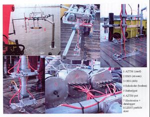
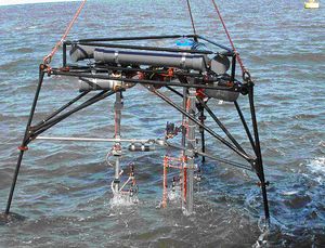
- stand-alone sampling from frames/tripods/poles on/in the seabed or from drift bouys (profiling mode from surface to bed) using a package of sophisticated electronic sensors (electromagnetic and acoustic flow meters, optical and acoustic backscattering sediment concentration meters); see Figures 2 and 3.
A typical instrument package attached to a stand-alone tripod in coastal environments is, as follows:
- electromagnetic point velocity meters (EMV), acoustic Doppler point velocity meters (ADV) and acoustic Doppler Current Profilers (ADCP);
- optical backscatter point sensors (OBS) for silt/mud; acoustic backscatter point sensors (ASTM) and acoustic backscatter profiler (ABS) for sand;
- in-situ Laser diffraction sensors (LISST) for particle size;
acoustic bed profiler (line and sector scanning) for bed and ripple pattern detection.
A problem of all stand-alone facilities is the wave and current-induced scour near the legs of the structures involved and the scour underneath and around the instrument sensors. Black and Rosenberg (1991[6]) have found by camera observations that a minimum distance of about 0.05 m should be kept between the probe (sensor) and the bed in oscillatory flow conditions to prevent scour of bed material. The free span of the instrument supports and legs should always be as large as possible to allow measurements between the legs with minimum disturbance. A dramatic example of a poorly designed research pier is the Duck Pier (North Carolina, USA) with a longshore pile spacing is 4.6 m and cross-shore spacing is 12.2 m, which has caused considerable scour in the vicinity of the pier. An example of a slender pier with cross-shore pile spacings of 36 m is the Sally Wharf near Bordeaux, France (Figure 1).
Stand-alone tripods (Figures 2 and 3) are placed on the seabed from a vessel during calm conditions. They are vulnerable in high wave conditions (overturning) or in areas with intensive fishing activities. Another problem is the absence of control of the measuring elevations of the instruments in conditions with rapidly changing bed levels (surf zone). The instruments can be damaged easily when placed close to the bed. Williams et al. (2003[7]) concluded that the turbulence levels underneath their tripod was slightly increased. The bed-shear stresses were also slightly over-estimated (15%). Evidence of scour in the immediate vicinity of the legs was detected, but was sufficiently localised not to effect the ripples beneath the main instrument package on the tripod.
Piles/poles driven or washed into the bed offer a simple solution for hydrodynamic measurements of waves and winds, but cannot be used for measurements of velocities and sediment concentrations due to the influence of vortices and scour generated by the pile/pole construction.
Towed sledges or trailers with a mast above the water surface have been used for cross-shore bed level soundings and wave height measurements in the surf zone during storms. However, they cannot be used for measurements of velocities and sediment concentrations due to the disturbing influence of vortices generated by the structure itself.
Reviews of field instrumentation for the coastal environment have been given by Terwindt et al. (1992[8]), Basinski (1989[9]) and White (1998[10]).
See also
Summaries of the manual
- Manual Sediment Transport Measurements in Rivers, Estuaries and Coastal Seas
- Chapter 1: Introduction, problems and approaches in sediment transport measurements
- Chapter 2: Definitions, processes and models in morphology
- Chapter 3: Principles, statistics and errors of measuring sediment transport
- Chapter 4: Computation of sediment transport and presentation of results
- Chapter 5: Measuring instruments for sediment transport
- Chapter 6: Measuring instruments for particle size and fall velocity
- Chapter 7: Measuring instruments for bed material sampling
- Chapter 8: Laboratory and in situ analysis of samples
- Chapter 9: In situ measurement of wet bulk density
- Chapter 10: Instruments for bed level detection
- Chapter 11: Argus video
- Chapter 12: Measuring instruments for fluid velocity, pressure and wave height
Other internal links
- Instrument characteristics of point-integrating suspended load samplers
- Guidelines for selection of sediment transport samplers
- Measuring instruments for rivers
- Measuring instruments for estuaries
External links
Further reading
- Davis, B.E., 2005.A guide to the proper selection and use of federally approved sediment and water-quality samplers. Report QQFederal Interagency Sedimentation Project (FISP), Waterways Experiment Station, Vickburg, USA (http://fisp.wes.army.mil).
- Edwards, T.K. and Glysson, G.D., 1999. Field methods for measurements of fluvial sediment. Techniques of water resources investigations of the US Geological Survey, Book 3, Applications of Hydraulics, Chapter C2. USGS, Box 25286, Denver CO 80225, USA.
- Grasmeijer, B.T. et al., 2005. Description of measurements and database of field and laboratory data, Paper M. In: Sandpit edited by Van Rijn et al., 2005. ISBN 90-800356-7-X (http://www.aquapublications.nl).
- Guy, H.P.,Fluvial sediment concepts. Techniques of water resources investigations of the US Geological Survey, Book 3, Applications of Hydraulics, Chapter C1. USGS, Box 25286, Denver CO 80225, USA.
- Hemsley, J.M., McGehee, D.D. and Kucharski, W.M., 1991. Nearshore oceanographic measurements: Hints on how to make them. Journal of Coastal Research, Vol. 7, No. 2.
- Rijkswaterstaat/RIZA, 2001.Autonomous Measuring Facility for measurement of water and sediment movements (in Dutch). Report RIZA 2001.073X, Lelystad, The Netherlands.
References
- ↑ Rijn, L. C. van (1986). Manual sediment transport measurements. Delft, The Netherlands: Delft Hydraulics Laboratory
- ↑ Katori, S., 1983.Measurement of Sediment Transport by Streamer Trap (In Japanese). Report No. 17, TR-82-1, Nearshore Environment Research Center, Japan.
- ↑ 3.0 3.1 3.2 Antsyferov, S.M., Belberov, Z.K. and Massel, S., 1990.Dynamical Processes in Coastal Regions Publishing House, Bulgarian Academy of Sciences.
- ↑ 4.0 4.1 Kraus, N.C., 1987.Application of Portable Traps for Obtaining Point Measurements of Sediment Transport Rates in the Surf Zone. Journal of Coastal Research, Vol. 3, No. 2.
- ↑ Kana, T.W., 1979. Suspended Sediment in Breaking Waves. Techn, Report No. 18-CRD, Coastal Res. Div., Dep. of Geology, Univ. of South Carolina, Colombia, USA.
- ↑ Black, K.P. and Rosenberg, M.A., 1991.Hydrodynamics and Sediment Dynamics in Wave-Driven Environments, Technical Report No. 13, Victorian Institute of Marine Science, Victoria, Australia.
- ↑ Williams, J.J. et al., 2003.Interactions between a benthic tripod and waves on a sandy bed. Continental Shelf Research, Vol. 23, p. 355-375.
- ↑ Terwindt, J.H.J, Greenwood, B.J. and Short, A., 1992. Users report on instruments for coastal research. Dep. of Physical Geography, University of Utrecht, Utrecht, The Netherlands.
- ↑ Basinski, T., 1989. Field studies on sand movement in the coastal zone. Polska Akademia Nank, Instytut Budownictwa Wodnego, Gdansk, Poland.
- ↑ White, T.E., 1998. Status of measurement techniques for coastal sediment transport. Coastal Engineering, 35, p. 17-45.
Please note that others may also have edited the contents of this article.
|
Please note that others may also have edited the contents of this article.
|


