Salinity sensors
Contents
Practical Salinity
In the course of time, various methods have been developed to determine the salinity of seawater, see the article Salinity. The most practical method currently used is through electrical conductivity. Because this is an indirect method, an accurate relationship has been established between the conductivity [math]C[/math] and the salinity [math]S[/math] as a function of temperature [math]T[/math] and pressure [math]p[/math]. The salinity determined in this way is called the 'practical salinity'. The accuracy with which the conductivity of seawater can be measured is limited for reasons listed later in this article. Possible measurement errors can be eliminated, at least partly, by considering the relative conductivity [math]R[/math], the seawater conductivity [math]C(S,T)[/math] relative to the conductivity [math]C(35,15)[/math] of a standard saline solution at 15oC containing 32.4356 g KCl in a mass of 1 kg. The salinity of this standard solution is exactly 35. We omit pressure because it is only relevant for the deep ocean. The relationship between the salinity [math]S(T)[/math] and the relative conductivity [math]R=R(S,T)[/math] reads:
[math]S(T) = S(15) + \Delta S(T) , \qquad R=\Large\frac{C(S,T)}{C(35,15)}\normalsize , \qquad (1)[/math]
[math]S(15)=0.008-0.1692\,R^{1/2}+25.3851\,R+14.0941\,R{3/2}-7.0261\,R^2+2.7081\,R^{5/2} , \qquad (2)[/math]
[math]\Delta S(T)= \Large\frac{T-15}{1+0.0162(T-15)}\normalsize (0.0005-0.0056\,R^{1/2} -0.0066\,R-0.0375\,R^{3/2}+0.0636\,R^2-0.0144\,R^{5/2}) , \qquad (3)[/math]
for [math] 2 \, \le S \le \, 42 [/math]. If R=1 we have S=35.
Sensors
Platinum Electrode Conductivity Sensor
As the practical salinity is not a physical parameter that can be measured directly, “Salinity Sensors” do not exist. What is commonly referred to as a salinity sensor is in fact a conductivity sensor.
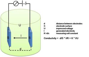
This Conductivity Sensor measures the ability of a solution to conduct an electric current between two electrodes. In solution, the current flows by ion transport; therefore, an increasing concentration of ions in the solution will result in higher conductivity values. Conductance is defined as the reciprocal of resistance. When resistance is measured in ohms, conductance is measured using the SI unit, siemens (formerly known as a mho). Since the siemens is a very large unit, aqueous samples are commonly measured in microsiemens, or µS.

Conductivity, [math]C[/math], is found using the following formula:
[math]C=G\cdot kc , \qquad (4)[/math]
where [math]G[/math] is the conductance, and [math]kc[/math] is the cell constant. The cell constant is determined for a probe using the following formula:
[math]kc = \Large\frac{d}{A}\normalsize , \qquad (5)[/math]
where [math] d [/math] is the distance between the two electrodes, and [math]A[/math] is the area of the electrode surface. The conductivity value is found by multiplying conductance and the cell constant. A potential difference is applied to the two probe electrodes in the Salinity Sensor. The resulting current is proportional to the conductivity of the solution. This current is converted into a voltage.
Electrodeless Conductivity Sensor (Inductive)
Electrodeless conductivity sensors use inductive coils. The inductive conductivity sensor consists of two coils which are incorporated next to one another in a polymer or ceramic body. These coils form current transformers. The sensor is designed so part of the liquid media forms a closed conductive current path passing through the coils. Current is applied to the primary coil (generating coil), which induces an alternating voltage in the liquid loop. In liquids which conduct electricity, this causes a current flow captured by the second coil (receiving coil), which is proportional to the conductivity of the sample solution.
Comparing the sensors
Electrode Sensors
- The main advantages of electrode sensors are:
- there is no proximity effect, the sensor can be mounted next to other sensors without interference
- easily calibrated in small baths
- The main disadvantages are:
- any changes in the cell constant will be reflected in the conductivity, and the cell cannot be cleaned in the field
- electrodes are subject to corrosion or damage (however, most sensors used in oceanography are inside a cell that prevents this, as shown in the image above)
- electrodes inside a cell need seawater pumping which limits the measuring rate
Inductive Sensors
- The main advantages of inductive sensors are:
- robust construction
- they can be cleaned with soap or solvents and a brush.
- there are no electrodes, so there is no possibility of their damage.
- The main disadvantages are:
- a significant part of the measurement is external leading to major consequences resulting from this external field. The inductive sensors require a 3 inches radius from any other surface, from adjacent sensors. It is particularly difficult to address this problem in companion mounts such as ARGO floats or biological fouling.
- mounting and calibration of the sensor to companion packages (Argo floats, current meters, AUVs, etc.) must be undertaken to avoid intrusion into the external area. Because final package geometry influences the results, the calibration must be performed on the fully assembled package.
Calibration
- Zero Calibration Point: Simply perform this calibration point with the probe out of any liquid or solution (e.g., in the air). A very small voltage reading will be read. Call this value 0 ppt.
- Standard Solution Calibration Point: Place the Salinity Sensor into a standard solution (solution of known concentration). Wait for the displayed voltage to stabilize. Enter the value of the standard solution (e.g., 35).
Related articles
Please note that others may also have edited the contents of this article.
|

