Delft Nile bed load and suspended load sampler (DNS)
This article is a summary of sub-section 5.5.1.4 of the Manual Sediment Transport Measurements in Rivers, Estuaries and Coastal Seas [1]. The Delft Nile Sampler can be used to measure the bed load and the suspended load.
Contents
Delft Nile sampler (DNS)
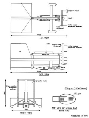
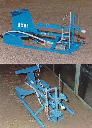
The instrument consists of a bed-load sampler and a suspended load sampler attached to a supporting frame (see Figure 1 and 2). The sampler has a weight of about 60 kg. The suspended load sampler consists of 7 intake nozzles (inner diameter = 0.003 m) which are connected to plastic hoses and operated by pumps. The bed-load sampler consists of a nozzle (entrance width = 0.096 m, entrance height = 0.055 m, length = 0.085 m, rear width = 0.105 m, rear height = 0.06 m) connected to a bag. The bag consists of nylon material with a mesh size of 150 or 250 um, depending on the size of bed material. At the upper side of the bag a patch (0.10 x 0.15 m(sup>2) consisting of 500 um material is present to reduce the blocking effect by fine particles as much as possible (see Figure 1). The bottom side of the sampler nozzle has a forward-tilting slope of 1 to 10. The bed-load sampler is connected to a swing arm, which can move in the vertical direction (upward and downward) over a distance of about 0.15 m with respect to the supporting frame. In its hanging position during lowering of the instrument, the bed-load sampler is in its most upward position. When the frame of the instrument is placed on the bed, the sampler nozzle makes contact with the bed by relaxing the tension in the cable. When the instrument is raised, first the nozzle of the bed-load sampler is raised over 0.15 m and then the frame is lifted from the bed. The swing-arm construction was designed to reduce the gap effect and the scooping effect as much as possible. The instrument was developed for bed-load measurements in the Nile river.
The hydraulic coefficients of the 250 um -bag and the 150 um -bag, both with a patch of 500 um at the upper side, are about unity for filling percentages in the range of 0% to 50%. A filling percentage of 75% reduces the hydraulic coefficient to about 0.75. The hydraulic coefficient of an impermeable plastic bag with a patch of 500 m at the upper side, simulating a blocked nylon bag, is about 0.8 for a filling percentage in the range of 0% to 50%. A filling percentage of 75% reduces the hydraulic coefficient to about 0.70. Based on these results, a maximum filling percentage of 50% is advised to be used. Blocking of the nylon material by fine sediments will result in a hydraulic coefficient of about 0.8.
The sampling efficiency is defined as the ratio of the bed-load transport measured by the sampler at a certain location during a certain period and the true bed-load transport at the same location during the same period (if the sampler had not been there). The sampling efficiency will express sampling errors related to the initial and scooping effect, the gap effect and the loss of sediment particles through the patch of the bag.
The bed-load transport (in kg/sm) can be determined as:
[math]S_b=k\,G_s\,-G_o\,/(bT)[/math]
in which:
- [math]k\,[/math]= calibration factor (= 1 to 1.5),
- [math]G_s\,[/math]= dry mass of sediment catch (kg),
- [math]G_o\,[/math] = dry mass of sediment catch related to initial and scooping effect determined by ‘zero-sampling’ (sampler is lowered to bed and immediately raised),
- [math]b\,[/math]= width of intake opening (= 0.096 m for DNS),
- [math]T\,[/math]= sampling period (s).
The Go-values should be determined by taking 10 zero-samplings at each location. Practical experience sofar shows a value of about 0.03 kg. The sampling efficiency (k-factor) was determined by means of tests in a flume at the Hydraulics and Sediment Research Institute in Deltabarrage, Egypt. Different velocity and sand size ranges were considered. The k-factor was found to be in the range of 1 to 1.5.
See also
Summaries of the manual
- Manual Sediment Transport Measurements in Rivers, Estuaries and Coastal Seas
- Chapter 1: Introduction, problems and approaches in sediment transport measurements
- Chapter 2: Definitions, processes and models in morphology
- Chapter 3: Principles, statistics and errors of measuring sediment transport
- Chapter 4: Computation of sediment transport and presentation of results
- Chapter 5: Measuring instruments for sediment transport
- Chapter 6: Measuring instruments for particle size and fall velocity
- Chapter 7: Measuring instruments for bed material sampling
- Chapter 8: Laboratory and in situ analysis of samples
- Chapter 9: In situ measurement of wet bulk density
- Chapter 10: Instruments for bed level detection
- Chapter 11: Argus video
- Chapter 12: Measuring instruments for fluid velocity, pressure and wave height
Other internal links
Further reading
- Van Rijn, L.C. and Gaweesh, M., 1992. A New Total Load Sampler. Journal of Hydraulic Engineering, Vol. 118, No. 12.
- Delft Hydraulics, 1991. Delft Nile Sampler; Bed Load Measurements in the River Waal. Report Q1300, part 1, Delft, The Netherlands.
- Delft Hydraulics, 1992. Bed Load Measurements in the River Waal near Woudrichem and near Druten. Report Q1300, part 2 and 3, Delft, The Netherlands.
References
- ↑ Rijn, L. C. van (1986). Manual sediment transport measurements. Delft, The Netherlands: Delft Hydraulics Laboratory
Please note that others may also have edited the contents of this article.
|
Please note that others may also have edited the contents of this article.
|

