Application of breakwaters
While detached breakwaters are the most common type of breakwater, many other types of breakwaters exist. These include submerged or low-crested breakwaters, floating breakwaters and special type breakwaters and will be described in this article.
Contents
Submerged or low-crested breakwaters
Submerged or low-crested breakwaters function by provoking wave-breaking and by allowing some wave transmission so that a milder wave climate is obtained in lee of the submerged structure, although it is not as mild as if the structure was emerged. The sediment transport capacity behind the breakwater will also decrease, which means that sand will accumulate in a manner similar to an emerged structure with a slightly smaller length. The wave-breaking and overtopping also mean mass transport of water over the structure. There is a close relationship between, on one hand, wave transmission and mass transport over the structure and reduction in the sand transport and, on the other hand, crest freeboard, crest width and wave height and steepness.
Reasons for selecting a submerged/low breakwater
- The visual impact of a submerged/low structure is less damaging
- A submerged or low-crested structure is less expensive
- The impact on the transport climate and on the sand accumulation is smoother
- The overtopping water generates good water circulation behind the breakwater
- Submerged breakwaters are very similar to natural reefs. They attract fish and are therefore popular among fishermen
Disadvantages of submerged/low crested breakwater
- A submerged structure can be dangerous for small craft navigation
- The overtopping water initiates local currents, which can be dangerous for swimmers
- A submerged or low-crested structure provides only partial attenuation of the wave action as well as partial shore protection and coast protection
- The efficiency of a submerged structure with respect to the attenuation of both waves and littoral transport and with respect to shore protection very much depends on the crest freeboard of the design. If there is considerable tide and storm surge at the location in the design situation, even a submerged or low crested structure will end up being rather high relative to the normal water-level. This means that one of the advantages of a low-crested structure, namely that it is not visible most of the time, cannot be obtained
- The design is very difficult and challenging because the proper function of a submerged or low-crested structure depends on both water-level and wave conditions as well as on the specific structure.
Floating breakwaters
Floating breakwaters work by dissipating and reflecting part of the wave energy. No surplus water is brought into the sheltered area in this situation. Floating breakwaters are normally used as piers in marinas, but they are also used as protective structures for marinas in semi-protected areas. They are especially suited for areas where the tidal range is high, as they follow the water-level. Floating breakwaters are seldom used as shoreline management structures because they are not suitable for installation in the open sea.
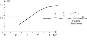
The wave transmission coefficient Ht/Hi, i.e. the ratio between the height of the transmitted wave and the height of the incoming wave, depends very much on the ratio L/w between the wavelength L and the width of the floating structure w. As a rule-of-thumb the transmission varies between Ht/Hi = 0.3 for L/w = 3 and Ht/Hi = 0.9 – 1.0 for L/w = 8, see Fig. 1. below.
Consider the example of a pontoon width of w = 3 m, and a requirement of a wave transmission of min. Ht/Hi = 0.5. In this case the wavelength should be smaller than L < 4.2w = 12.6 m, which corresponds to an approximate wave period of T = 2.9 seconds. Floating breakwaters can only be used in waters of very limited fetch. Floating breakwaters thus cannot be used as shoreline management structures at moderately exposed and exposed locations. For more information on different types of floating breakwaters, see the article floating breakwaters.
Modified breakwaters and headlands
Background
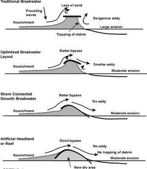
The supporting structures for coastal restoration schemes have, in the preceding discussions, mainly been traditional groynes and breakwaters. Various unwanted effects associated with these structures have also been highlighted. This subsection discusses possible modifications to the layout of traditional structures to minimise these unwanted effects, see also Fig. 2.
The philosophy behind the optimisation of the traditional, coast-parallel breakwater into an artificial headland (Fig. 2.) is as follows:
- To improve the bypass and to minimise offshore loss as well as lee side erosion
- To eliminate dangerous rip currents as well as lee areas, which may otherwise trap debris
- To enhance the aesthetic appearance and to gain some useful land.
Functional characteristics
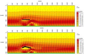
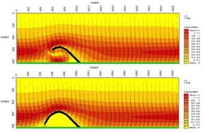
The initial current patterns for these structures are illustrated in Fig. 3. These current patterns only show the initial situation without nourishment so they are not fully applicable in evaluating the conditions after initial fill or trapping of sand has taken place. However, they are useful as indicators of how the different schemes will function. The following characteristic conditions are important.
Important characteristics
- Comparing a and b: The curved breakwater guides a larger amount of longshore current (and the littoral transport) around the structure on the offshore side, but turning the flow slightly towards the shore, it provides better bypass and less lee side erosion. The eddy in the lee area downstream of the structure is smaller for the curved structure, but it is still there. The scour hole at the lee end is evaluated to be smaller.
- Comparing b and c: The breakwater connected to the shore provides a very smooth passage for the longshore current (and the littoral transport) around the structure, thereby providing optimal bypass and less lee side erosion. The eddy at the downstream side no longer exists, which improves the safety for swimmers and reduces the trapping of seaweed and debris. The internal current pattern of the area sheltered by the structure is not relevant because this area will be filled with sand. This sandy area will become very attractive for recreational activities.
- Comparing c and d: The headland acts more or less like the breakwater connected to the shore; the only difference is a smoother transition of the longshore current (and the littoral transport) at the upstream end of the structure. This is due to the smooth transition between the coast and the structure in the case of the headland. The transition will be even more smooth if sand fill is introduced upstream of the headland. There is no eddy at the downstream side, which improves the safety for swimmers and reduces the trapping of seaweed and debris. If the reclaimed area is sufficiently elevated, it can be used for permanent recreational installations.
The headland can also be partly submerged, whereby it will act as a headland continuing into a reef. Careful design will make this type of headland appear almost natural.
Applicability
The curved breakwater, the breakwater connected to the shore and the headland are useful substitutes for traditional groynes and breakwaters on coastal types 1 and 2.
The curved breakwater can be used for all types of coasts, where traditional breakwaters can be used, see above.
Neither the breakwater connected to the shore nor the headland can be used as replacements for traditional segmented breakwaters with small gaps and pocket beaches.
See also
References
- Mangor, Karsten. 2004. “Shoreline Management Guidelines”. DHI Water and Environment, 294pg.
Please note that others may also have edited the contents of this article.
|


