Detached breakwaters
Contents
Introduction
Detached breakwaters aim to protect a coast or activities along the coastline (e.g. ports, ship wharf) from wave action. In general terms, a detached breakwater is a coast-parallel structure located inside or close to the surf-zone. Several types of breakwaters exist, from which detached breakwaters are the most common type. This article provides a general introduction of detached breakwaters and describes emerged breakwaters, submerged or low-crested breakwaters, floating breakwaters and other special type breakwaters. Different aspects of breakwaters as coastal protection are discussed, as well as their impacts on shoreline evolution.
Most of the content of this article is drawn from Mangor et al. 2017 [1]. A special type of detached breakwaters is dealt with in the article Artificial reefs.
Breakwater schemes have many variables. The following characteristics determine the impact on the shoreline:
- Emerged, submerged or floating
- Distance from shoreline and location relative to the surf zone
- Length and orientation
- Single or segmented
- Special shapes
A shoreline management breakwater serves two purposes:
- To provide shelter from waves
- Through this shelter, to manipulate the littoral transport conditions and thereby to trap some sand
Single emerged detached breakwaters
A detached breakwater provides shelter from the waves, whereby the littoral transport behind the breakwater is decreased and the transport pattern adjacent to the breakwater is modified. These characteristics of a breakwater are utilised in different ways for various types of breakwaters by varying relevant parameters. There are three different types of breakwaters, schematically indicated in Fig.1.:
- Offshore breakwaters
- Coastal breakwaters
- Beach breakwaters
The first type is generally used as ship berth, whereas the latter two types of breakwaters are mainly used for shoreline management.
Characteristic parameters
A detached emerged breakwater can be characterized by the following parameters (Fig.2):
The most important parameters are:
- [math]L_B[/math] Length of the breakwater
- [math]x[/math] Breakwater distance to shoreline
- [math]x_{80}[/math] Surf-zone width, approximately 80 % of the littoral transport takes place landwards of this line
Dimensionless length and distance:
- [math]L_B^*=L_B/x[/math] Breakwater length relative to breakwater distance to shoreline
- [math]x^*=x/x_{80}[/math] Breakwater distance relative to surf-zone width
Accumulation forms:
- Salient: When the dimensionless breakwater length [math]L_B^*[/math] is less than approx. 0.6 to 0.7, a bell-shaped salient in the shoreline will form in the lee of the breakwater. However, parameters other than the breakwater length and distance also influence the accumulation pattern.
- Tombolo: When the dimensionless breakwater length [math]L_B^*[/math] is greater than approx. 0.9 to 1.0, the sand accumulation behind the breakwater will connect the beach to the breakwater in a tombolo formation. But again, parameters other than the breakwater length and distance influence the accumulation pattern.
If there are several breakwaters in a series, this is referred to as a segmented breakwater, where the length of the gap between the breakwaters is denoted:
- [math]L_G[/math] Length of gap between breakwaters in a segmented breakwater
Offshore breakwaters
Offshore breakwaters are located far outside the surf zone, [math]x^*\gt 3[/math], see Fig.1. The purpose of an offshore breakwater is normally to protect an offshore ship wharf against wave action, which means that an offshore breakwater is a special type of port, as illustrated in Fig.3. The offshore breakwater is often used when the slope of the coastal profile is small. At such locations, a traditional port would have to extend far from the shoreline or extensive dredging works would have to be carried out to provide access to the port. In order to minimize the works and to avoid the associated impact, an offshore breakwater may be the answer. Offshore breakwaters are normally located at a slightly greater water depth than is required for navigation, thus avoiding/minimizing capital dredging and minimizing sedimentation. They are designed:
- to provide shelter for a wharf,
- to minimize sedimentation, and
- to minimize the impact on the coastline.
Offshore breakwaters are therefore placed as far away from the surf-zone as possible and they are as short as possible to minimize the impact on coastal morphology. However, experience shows that this is very difficult to obtain in practice; offshore-detached breakwaters often cause accumulation in their lee zone resulting in erosion effects in adjacent areas. It is thus important that the coastal impact of offshore breakwaters is taken into account when carrying out an environmental impact assessment for a port. In the ideal case offshore breakwaters hardly influence coastal morphology; they will therefore not be discussed any further in this article.
Coastal and beach breakwaters
Coastal breakwaters are located within a distance from the shoreline of half the width of the surf-zone, up to twice the width of the surf-zone, [math]0.5 \lt x^* \lt 2[/math], see Fig.1. Such breakwaters trap sand within the part of the littoral zone they cover, thus securing that part of the coastal profile against erosion, as illustrated in Fig.4.
Beach breakwaters are located within less than half the width of the surf-zone from the shoreline, [math]x^* \lt 0.5[/math], see Fig.1. Beach breakwaters trap sand on the foreshore without interfering significantly with the overall transport pattern, as illustrated in Fig.5.
Coastal and beach breakwaters are designed:
- to partly provide wave shelter for a certain part of the shore and the coast
- to modify the littoral transport in a predictable way, so that the combined shore-restoration and coastal protection function can be properly designed.
The extent of the sand trapping, or the ability to establish the desired sand accumulation pattern, is mainly regulated by choosing the length of the breakwater, the distance of the breakwater to the shore and the number of single breakwaters in a segmented breakwater and, finally, the length of the gaps.
The advantage of a breakwater in comparison to a groyne is that it is possible to modify the littoral transport in a smoother manner than for a groyne. In this way there will be less lee side erosion on the downstream shoreline. This applies especially to breakwaters, which are so short that a permanent tombolo does not develop.
Sometimes coastal breakwaters are planned so as to provide shelter for the beach landing of small fishing boats or sheltered water for swimming. This is difficult as sufficient shelter for the boats and the swimmers requires such a long breakwater that a tombolo develops. When the tombolo has developed there is no sheltered water area left for boat landing and swimming, only a semi-protected bay downstream of the tombolo is left. This bay may be suitable for landing small boats, but it is certainly not suitable for swimming during rough wave conditions due to the eddy, which will always be present during such conditions.
Sand will be trapped behind a breakwater if initial sand fill is not performed. The trapped sand comes from the adjacent beaches, which means that both the upstream and downstream beach will suffer from erosion during the development of a salient or a tombolo. When a tombolo has been formed, the adjacent beaches are influenced in a way similar to that of a groyne with upstream accretion and lee side erosion. The influence of a salient will be smoother.
Impacts of breakwaters
Hydrodynamic impacts
A detached breakwater produces several impacts on the hydrodynamic conditions in the adjacent area:
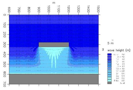
- The breakwater shelters partly from the waves; however, as the waves diffract into the sheltered area, a complete shelter cannot be obtained. The longer the breakwater, the better the shelter. Submerged and floating breakwaters provide less shelter.
- Wave-overtopping of submerged or low breakwaters will cause an additional supply of water in the area behind the breakwater, and consequently some compensation currents running out the sheltered area.
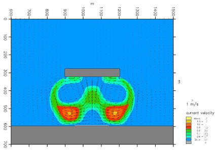
- The wave set-up on the foreshore is less in the sheltered area than outside, which generates local currents towards the sheltered area along the foreshore from both sides of the breakwater so that two eddies develop. These eddies also develop in the case of oblique wave approach.
- The longshore current is partially blocked by the circulation currents; this causes some of the longshore currents to be diverted outside the breakwater.
Morphological impact
By modifying hydrodynamic conditions, detached breakwaters impact on the morphological conditions in several ways:
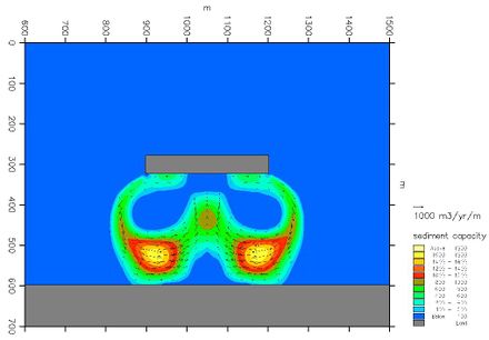
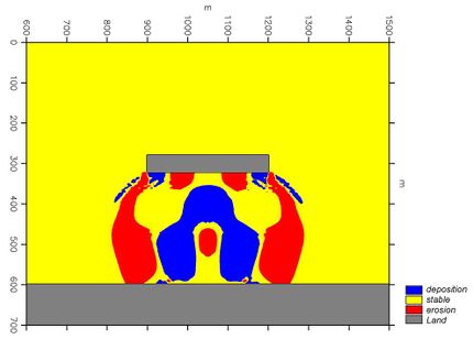
- The littoral transport in the lee of the breakwater decreases due to wave attenuation and weakened longshore currents in the area sheltered by the breakwater. This causes trapping of sand behind the breakwater depending on the local setting. As a rule-of- thumb, the trapping of sand will develop into a tombolo formation connecting the breakwater and the shore by sand deposits, if the length of the breakwater is equal to or longer than 0.8 times the distance between the shore and the breakwater. For shorter breakwaters, only a salient in the shoreline will develop.
- The diversion of the longshore currents will cause the development of local erosion close to the heads of the breakwater.
- The trapping of sand, especially if a tombolo has developed, will cause lee side erosion downdrift of the breakwater. This downdrift erosion is very similar to what is developed for groynes. However, there are more parameters involved in breakwaters, so it is possible to manipulate the transport in a more refined manner.
- A breakwater traps sand under all circumstances, even if the net transport is zero. This means also that there will be a coastal impact in any case.
- Fig.7. Initial sediment transport pattern and initial morphological impact caused by a detached breakwater for perpendicular wave approach.
When several breakwaters are constructed in a row, the system is referred to as a segmented breakwater. A segmented breakwater is used to protect long sections of shoreline; the downstream coastal impact will be correspondingly larger than for a single breakwater.
Other impacts
Other impacts by breakwaters:
- If segmented breakwaters are constructed with too small gaps, the water exchange in the embayments between the breakwaters may be poor.
- Breakwaters normally obstruct part of the view over the sea, which means that the visual impact can be unacceptable.
- Swimmers may feel tempted to use the sheltered area in connection with detached breakwaters, but the circulation currents can be dangerous.
Influence on flow patterns
The influence of various coastal breakwaters on the flow pattern of the longshore current is illustrated for two breakwaters, one relatively long and the other one relatively short. The dimensions of the breakwaters are:
| [math]L_B[/math] | [math]x[/math] | [math]x_{80}[/math] | [math]L_B^*[/math] | [math]x^*[/math] | |
| The long breakwater | 312 m | 240 m | 250 m | 1.3 | 0.96 |
| The short breakwater | 144 m | 240 m | 250 m | 0.6 | 0.96 |
The bathymetry considered here is a plane beach with constant slope of 1:50; irregular and directional waves with [math]H_s[/math]= 2.8 m, [math]T_s[/math]= 8.0 s and deep-water wave incident angle [math]\alpha_0=12^o[/math] are assumed. The flow pattern after the construction of the breakwaters is simulated by applying DHI’s numerical model system MIKE 21. Two modules have been applied, the parabolic mild slope wave module and the depth-integrated hydrodynamic module, MIKE 21 PMS and HD, respectively. The computed flow patterns for these two breakwaters are presented in Fig.8.
Long breakwater
The long breakwater causes major changes in the flow pattern. There are increasing current speeds towards the lee zone, high current speeds close to the breakwater heads and circulation in the downstream end of the lee zone. This current pattern and the corresponding sediment transport pattern cause the formation of a tombolo. There will also be local scour close to the breakwater heads. The eddy in the lee zone will remain, even after the tombolo has formed, and the current around the upstream head of the breakwater will increase with a higher offshore component. The current eddy and the scour holes will be dangerous for swimmers, and the jet directed offshore will cause a loss of sand and decreased bypass, resulting in relatively large lee side erosion. The local lee bay will tend to collect seaweed and debris. Furthermore, the tombolo provides easy access to the breakwater, which is not practical, as walking on the structure and jumping from it can be dangerous.
Short breakwater
If the breakwater is fairly short, the flow pattern will be quite different, as shown in Fig. 8 upper panel. There will be no high currents at the breakwater heads; there will be only a minor tendency for eddy formation and there will be only slight changes in the general pattern of the longshore current. The morphological response to such a breakwater will be a smooth salient in the shoreline; a tombolo will not form and there will be no scour holes at the end of the breakwater heads. There will be no offshore loss of material, and the lee side erosion will be mild. These are all positive effects; the negative effect is that the protection, provided by a short breakwater, is limited. It will secure a wider beach locally, but it will not be able to stabilize a long section of shoreline by a stable sand sheet. If the sand sheet consists of nourished sand, frequent re-nourishment will be necessary.
Optimization of the breakwater design
The optimal solution is probably somewhere between a long and a short breakwater. It must form a solid salient, but not a tombolo. This solution is balanced between the requirements for coast and shore protection, the minimization of downstream impacts and seaweed trapping, and the optimisation of safety. Other modifications to the breakwater can also be considered. This will be discussed under the heading: Modified breakwaters and headlands.
Segmented emerged detached breakwaters
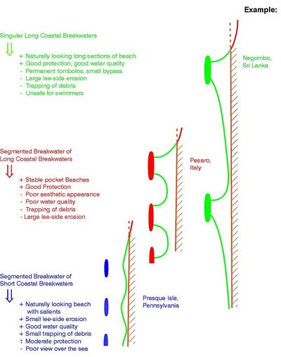
The above discussion was related to single breakwaters, but shoreline management schemes often utilize segmented breakwaters. A segmented breakwater scheme provides many possibilities, ranging from total coastal protection to mild shore protection. Fig. 9. shows the characteristic shoreline development, which can be obtained with segmented breakwaters with various combinations of breakwater lengths and gap widths.
A mixture of seawalls, revetments, groynes and breakwaters has, in the past, often been used in densely populated areas as coastal protection against long-term erosion. In some places the protection was coordinated, but most often it was everybody’s individual fight against the sea. Such areas are characterized by lost beaches, poor passage along the coastline and poor aesthetic appearance. The natural beauty of the coastal landscape is lost due to coastal protection measures and erosion continues. Such areas require an urgent upgrade to secure the values behind the coastline, as required by the landowners, and to re-establish the shore to the highest possible level, as required by the public and the authorities. This calls for a well-coordinated shoreline management scheme. With modern techniques and sufficient funds, it will be possible to upgrade the spoiled coastline to a nearly natural condition. However, it is almost impossible to re-establish the active coastal cliff, which is also a valuable coastal resource. The only way to achieve this is to allow the natural coastal erosion to continue. However, this requires that the authorities purchase the coastal land and allow it to develop naturally. In most cases this is unrealistic, but one solution may be to leave public-owned sections without protection, provided they are of a suitable length.
In such heavily populated and mostly privately owned areas, it will normally not be practical to choose a solution using nourishment alone, as it will not provide sufficient safety against coastal erosion, and as it is also difficult to manage. In this case a segmented breakwater scheme is a good choice, and it can be tailored to suit the requirements agreed upon by the interested parties. A pure nourishment solution requires substantial funds and public involvement.
The numerous possibilities are illustrated by the three very different schemes sketched in Fig. 9. It is evident that nearly all combinations of requirements can be met. The most difficult aspect of such projects is often the public and political process, which has to be carried through to reach consensus. The importance of this process must not be underestimated in the planning process.
Submerged or low-crested breakwaters
Submerged or low-crested breakwaters function by provoking wave-breaking and by allowing some wave transmission so that a milder wave climate is obtained in the lee of the submerged structure, although it is not as mild as if the structure was emerged. The sediment transport capacity behind the breakwater will also decrease, which means that sand will accumulate in a manner similar to an emerged structure with a slightly smaller length. The wave-breaking and overtopping also mean mass transport of water over the structure. There is a close relationship between, on one hand, wave transmission and mass transport over the structure and reduction in the sand transport and, on the other hand, crest freeboard, crest width and wave height and steepness.
Reasons for selecting a submerged/low breakwater
- The visual impact of a submerged/low structure is less damaging
- A submerged or low-crested structure is less expensive
- The impact on the transport climate and on the sand accumulation is smoother
- The overtopping water generates good water circulation behind the breakwater
- Submerged breakwaters are very similar to natural reefs. They attract fish and are therefore popular among fishermen
Disadvantages of submerged/low crested breakwater
- A submerged structure can be dangerous for small craft navigation
- The overtopping water initiates local currents, which can be dangerous for swimmers
- A submerged or low-crested structure provides only partial attenuation of the wave action as well as partial shore protection and coast protection
- The efficiency of a submerged structure with respect to the attenuation of both waves and littoral transport and with respect to shore protection very much depends on the crest freeboard of the design. If the low-crested structure is designed for conditions of high tide and storm surge it should be rather high relative to the normal water-level. This means that one of the advantages of a low-crested structure, namely that it is not visible most of the time, cannot be obtained
- The design is difficult and challenging because the proper function of a submerged or low-crested structure depends on both water-level and wave conditions as well as on the specific structure.
Floating breakwaters
Floating breakwaters work by dissipating and reflecting part of the wave energy. No surplus water is brought into the sheltered area in this situation. Floating breakwaters are normally used as piers in marinas, but they are also used as protective structures for marinas in semi-protected areas. They are especially suited for areas where the tidal range is high, as they follow the water-level. Floating breakwaters are seldom used as shoreline management structures because they are not suitable for installation in the open sea.
The wave transmission coefficient [math]H_t / H_i[/math], i.e. the ratio between the height of the transmitted wave and the height of the incoming wave, depends very much on the ratio [math]L/w[/math] between the wavelength [math]L[/math] and the width of the floating structure [math]w[/math]. As a rule-of-thumb the transmission varies between [math]H_t / H_i =0.3[/math] for [math]L/w=3[/math] and [math]H_t / H_i=0.9 – 1.0[/math] for [math]L/w=8[/math], see Fig.10.
Consider the example of a pontoon width of [math]w = 3 m[/math], and a requirement of a wave transmission of [math]H_t / H_i \lt 0.5[/math]. In this case the wavelength should be smaller than [math]L \lt 4.2 w = 12.6 m[/math], which corresponds to an approximate wave period of [math]T = 2.9 s[/math]. Floating breakwaters can only be used in waters of very limited fetch. Floating breakwaters thus cannot be used as shoreline management structures at moderately exposed and exposed locations. For a more discussion of different types of floating breakwaters, see the article Floating breakwaters.
Modified breakwaters and headlands
Background
The preceding sections and other articles on coastal protection measures (Human causes of coastal erosion, Groynes, Groynes as shore protection) are mainly dealing with traditional groynes and breakwaters. Various unwanted effects associated with these structures have been highlighted. This section discusses possible modifications to the layout of traditional structures to minimize these unwanted effects, see Fig.11.
Transforming the traditional, coast-parallel breakwater into an artificial headland can be decided for several reasons:
- to improve the bypass and to minimize offshore loss as well as lee side erosion
- to eliminate dangerous rip currents as well as lee areas, which may otherwise trap debris
- to enhance the aesthetic appearance and to gain some useful land.
The initial current patterns for these structures are illustrated in Fig.12. These current patterns only show the initial situation without nourishment so they are not fully applicable in evaluating the conditions after initial fill or trapping of sand has taken place. However, they are useful as indicators of how the different schemes will function. The following characteristic conditions are important.
Functional characteristics
- Comparing a and b: The curved breakwater guides a larger amount of longshore current (and the littoral drift) around the structure on the offshore side, but by turning the flow slightly towards the shore, it provides better bypass and less lee side erosion. The eddy in the lee area downstream of the structure is smaller for the curved structure, but it is still there. The scour hole at the lee end is evaluated to be smaller.
- Comparing b and c: The breakwater connected to the shore provides a very smooth passage for the longshore current (and the littoral drift) around the structure, thereby providing optimal bypass and less lee side erosion. The eddy at the downstream side no longer exists, which improves the safety for swimmers and reduces the trapping of seaweed and debris. The internal current pattern of the area sheltered by the structure is not relevant because this area will be filled with sand. This sandy area will become very attractive for recreational activities.
- Comparing c and d: The headland acts more or less like the breakwater connected to the shore; the only difference is a smoother transition of the longshore current (and the littoral transport) at the upstream end of the structure. This is due to the smooth transition between the coast and the structure in the case of the headland. The transition will be even smoother if sand fill is introduced upstream of the headland. There is no eddy at the downstream side, which improves the safety for swimmers and reduces the trapping of seaweed and debris. If the reclaimed area is sufficiently elevated, it can be used for permanent recreational installations.
The headland can also be partly submerged, whereby it will act as a headland continuing into a reef. Careful design will make this type of headland appear almost natural.
Application
The curved breakwater, the breakwater connected to the shore and the headland are useful substitutes for traditional groynes and breakwaters for moderately exposed coasts where the wave incidence angle is small. The curved breakwater can be used for all types of coasts, where traditional breakwaters can be used. Neither the breakwater connected to the shore nor the headland can be used as replacements for traditional segmented breakwaters with small gaps and associated pocket beaches.
Related articles
- Artificial reefs
- Human causes of coastal erosion
- Floating breakwaters
- Applicability of detached breakwaters
- Port breakwaters and coastal erosion
- Detached shore parallel breakwaters
- Hard coastal protection structures
- Dealing with coastal erosion
- Stability of rubble mound breakwaters and shore revetments
References
- ↑ Mangor, K., Drønen, N. K., Kaergaard, K.H. and Kristensen, N.E. 2017. Shoreline management guidelines. DHI https://www.dhigroup.com/marine-water/ebook-shoreline-management-guidelines
Please note that others may also have edited the contents of this article.
|


