Difference between revisions of "Light fields and optics in coastal waters"
(→Wavelength ranges) |
(→Introduction) |
||
| Line 4: | Line 4: | ||
===Introduction=== | ===Introduction=== | ||
| − | The quantitative study of underwater light fields in coastal waters and shelf seas has important applications in ecology, engineering and remote sensing. Underwater light fields: | + | The quantitative study of underwater light fields in coastal waters and shelf seas has important applications in ecology, engineering and [[remote sensing]]. Underwater light fields: |
# play an important role in determining rates of photosynthesis by phytoplankton and macrophytes, and therefore set limits on the productivity of marine ecosystems. | # play an important role in determining rates of photosynthesis by phytoplankton and macrophytes, and therefore set limits on the productivity of marine ecosystems. | ||
Revision as of 16:06, 5 December 2007

|
Contents
- 1 Underwater light fields
- 2 Light field descriptors
- 3 Optical properties of natural waters
- 4 Radiative transfer theory and light field modelling
- 5 Optical measurements in coastal waters
- 6 Regional characteristics
- 7 Implications for remote sensing
- 8 See also
- 9 References
Underwater light fields
Introduction
The quantitative study of underwater light fields in coastal waters and shelf seas has important applications in ecology, engineering and remote sensing. Underwater light fields:
- play an important role in determining rates of photosynthesis by phytoplankton and macrophytes, and therefore set limits on the productivity of marine ecosystems.
- influence the range at which objects are visible under water, which is of great significance for diving and engineering operations and also for visual interactions between predators and prey species.
- determine the volume reflectance of seawater which is important for optical remote sensing.
Dynamics of underwater light fields
Variations in underwater light fields originate from changes in both solar illumination and seawater composition, and predicting this variability involves the study of radiative transfer in an optically complex medium. There is an extensive literature on underwater light fields and associated problems in marine optics, but the fundamental concepts are clearly laid out in the books by Kirk (1994[1]), Mobley (1994[2]) and Bukata et al (1995[3]). One of the challenges posed by coastal light fields is the potential for interaction and between physical and biological factors. For example, sediment particles in suspension can limit the illumination of benthic photosynthetic organisms, but the presence of those organisms may stabilise the sediment surface and reduce the probability of sediment re-suspension taking place.
Underwater light fields are vulnerable to human activities. Anthropogenic disturbances such as eutrophication, dredging operations and accelerated soil erosion due to the de-afforestation of river catchments can modify underwater light climates in coastal regions. Increases in turbidity produced by these activities can damage important ecosystem components such as coral reefs and sea grass beds.
Variables
The underwater light field depends on:
- the optical characteristics of sea water: The optical characteristics of coastal waters are determined not only by water itself, but also by suspended particulate material (minerals, organic detritus and phytoplankton) and coloured dissolved organic matter. The presence of relatively high concentrations of dissolved organic matter or minerals often distinguishes coastal waters from those of deeper seas, and accounts for their green or brown colouration.
- the conditions of illumination: The conditions of illumination depend on solar angle, the degree and type of cloud cover, and the state of the sea surface. As a result, underwater light fields show strong diurnal and seasonal variability.
Light field descriptors
Radiance and irradiance
Radiance is the fundamental quantity in light field measurement. It is usually denoted L(q,f, l) where the angles q (zenith) and f (azimuth) specify the direction in which the radiance is measured and l is the wavelength. The units of radiance are W m-2 nm-1 sr-1. Measurements of the water-leaving radiance Lw just above the surface at q = 0 (nadir viewing) are particularly important for remote sensing. Planar and scalar irradiances Ex(l) are generated by integrating radiances over defined intervals of solid angle Dw. They have units of W m-2 nm-1. For planar irradiances, the radiances are multiplied by the cosine of their angle of incidence on the detecting plane before carrying out the integration. Scalar irradiances omit the cosine weighting. Measurements of planar irradiances are made using a diffusing disc as a collector, while scalar irradiances are measured use a diffusing sphere. Commonly used irradiances are summarized Table 1.
| Quantity | Name Definition | Angular limits |
|---|---|---|
| Eo(l) | Scalar irradiance | whole sphere |
| [Eo(l)]u | Upward scalar irradiance | lower hemisphere |
| [Eo(l)]d | Downward scalar irradiance | upper hemisphere |
| Eu(l) | Upward planar irradiance | lower hemisphere |
| Ed(l) | Downward planar irradiance | upper hemisphere |
A full description of an underwater light field would involve the specification of the spectral and angular distribution of radiance as a function of depth and geographical location, but this degree of detail is impractically cumbersome. The quantities most frequently specified are upward radiances and upward and downward irradiances.
Wavelength ranges
Studies of underwater light fields are usually contained within a waveband of approximately 300-900 nm: outside these boundaries, absorption by water strongly limits light penetration. Photosynthesis and animal vision mainly utilise the wavelength region of 400-700 nm, but damaging radiation can affect photosynthetic organisms at ultra-violet wavelengths (300-400 nm) while the near infra red region (700-900 nm) is important for remote sensing applications.
Measurement units
Three systems of units may be encountered in the literature on underwater light fields:
- Radiometric units: In physical radiometry, light energy is measured in joules (J), radiometric power in watts (W or J s-1), and the source brightness as power per unit solid angle (W sr-1).
- Quantum units: In photochemistry and photobiology, where molecular events are driven by the absorption of individual quanta, it is often useful to measure light fields in terms of numbers of photons rather than energy. A convenient unit is the mol (Avogadro’s Number) of photons. In the photobiology literature, one mol of photons is often referred to as an einstein, but the unit is redundant. The energy associated with a single photon of a given wavelength in vacuo is e = hc/l, where h is Planck’s constant and c the speed of light. The inverse wavelength dependence means that conversion between radiometric and quantum units (for example from W m-2 s-1 to mol photons m-2 s-1 in the case of irradiance) requires explicit knowledge of the spectral distribution of the light field. Integration of scalar quantum irradiance across the visible spectrum (400-700 nm) gives a measure of photosynthetically active radiation (PAR: mol photons m-2 s-1).
- Photometric units: The visual effect of a given source of illumination depends on the spectral sensitivity of the human eye. This leads to a system of photometric units based on the lumen as the measurement of effective power, and is discussed in DeCusatis (1997[4]). Conversion between radiometric and photometric units has to take both the standard eye response curve and the spectral distribution of the light field into account.
Optical properties of natural waters
Inherent optical properties (IOPs)
The optical characteristics of a light-transmitting medium can be specified in terms of its inherent optical properties, which represent the effect of an optically thin slab of the medium on the transmission of a collimated light beam. The main IOPs are:
- a: the absorption coefficient (m-1)
- b: the scattering coefficient (m-1)
- c = a + b: the attenuation coefficient (m-1)
- β: the scattering phase function (sr-1)
Formal definitions for these IOPs may be found in Mobley (1994[2]). The absorption, scattering and attenuation coefficients have fairly obvious meanings, while the phase function is a measure of the relative angular distribution of the scattered light. The scattering coefficient (b) is often partitioned into forward and backwards components, and the backscattering coefficient (bb) is of great importance for determining the remote sensing reflection of a water body.
IOPs and constituents
The total IOPs of a body of seawater can be considered as the sum of the partial contributions from water itself and a number of optically significant constituents. These constituents are generally divided into four classes:
- Phytoplankton cells and colonies (Phyt)
- Mineral suspended solids (MSS)
- Coloured dissolved organic matter (CDOM)
- Organic suspended solids or detritus (OSS)
The concentration of the photosynthetic pigment chlorophyll a (Chl, mg m-3) is often used as a proxy variable for phytoplankton biomass. Mineral particle and organic detritus concentrations (g m-3) are determined by filtering water samples through a fine glass fibre filter and measuring the dry weight of material retained before and after combusting the filter at 500o C to remove the organic portion. Since there is no standard method for measuring the mass concentration of coloured dissolved organic matter, it is conventionally measured as the absorption coefficient at 440 nm of seawater which has been passed through a membrane filter with a 0.2 μm pore size.
The total absorption coefficient can be written as the sum of the contributions of the individual constituents:
atotal = awater + aPhyt + aMSS + aCDOM + aOSS
The scattering coefficient (b), attenuation coefficient (c) and phase function (β) can all be partitioned in a similar manner. In practice, however, the optical contributions of these four classes of material may not be completely distinct: blooms formed by phytoplankton groups such as coccolithophores and diatoms may generate significant concentrations of mineral particles (calcite and silica respectively), and organic detrital material may form flocs which incorporate suspended minerals.
Specific optical properties of constituents
The optical contributions of the main classes of constituents can be calculated by multiplying the concentrations of each constituent by the value of its inherent properties expressed per unit concentration. The latter quantity is often referred to as a specific inherent optical property or specific optical cross section For example:
aMSS = MSS x a*MSS
where MSS is the concentration of suspended minerals and a*MSS is the specific absorption cross section for this constituent, with units of m2 g-1.
Optical characteristics of constituents
The convention that seawater contains four classes of optically significant constituents tends to conceal the fact that there can be considerable variability in specific optical properties within each class of constituent. Moreover, optical characterisation of the four main classes of constituent is currently incomplete.
CDOM
CDOM absorption has been extensively characterised. It is generally described by an exponential function of the form
- formula to be inserted
where (l0) is a reference wavelength (usually 440 nm) and S is a coefficient which has a typical value of 0.01 to 0.02 in UK coastal waters (Bricaud et al 1981[5]). Light scattering by CDOM is generally assumed negligible, but it is possible that some of the coloured material passing through 0.2 μm filters is colloidal in nature and therefore capable of contributing to the total scattering coefficient.
MSS
The optics of some types of mineral particles have been systematically explored (Babin and Stramski 2005[6]). Their absorption spectra are generally high in the blue wavebands and decrease towards the red, and for field samples their shape is often similar to that for CDOM. Scattering characteristics are influenced by size distribution and refractive index (Wozniak and Stramski 2004[7]). It is not clear whether laboratory samples of mineral dusts are representative of all the materials found in coastal locations.
Organic detritus
The optical properties of organic detritus are not well characterised. This is due to the wide range of material which falls under this classification, ranging from scenescent phytoplankton cells to faecal pellets in offshore waters and including terrestrial vegetable matter in estuaries. There is also the possibility that organic matter may form flocs which include mineral particles in estuaries and in post-bloom shelf-sea conditions.
Phytoplankton
A great deal of effort has been devoted to the study of the absorption and scattering characteristics of phytoplankton cells (see for example Sathyendranath et al 1987[8], Bricaud et al 1988[9] and Johnsen et al 1994[10]). The absorption spectra generally show maxima around the main chlorophyll absorption peaks at 440 nm and 675 nm, with subsidiary features depending on the presence of accessory light harvesting and photoprotective pigments. Phytoplankton scattering poses considerable practical and theoretical challenges because of the wide range of size and structure exhibited by individual cells and colonies. A helpful review of the theoretical problems is given by Quirantes and Bernard (2004[11]) and measurement issues are discussed in Volten et al.(1998[12]). For all but the smallest species, phytoplankton scattering is strongly peaked in the forward direction. One interesting feature in the total scattering spectra is the presence of minima near the chlorophyll absorption peaks which is due to Kettler-Helmholtz anomalous dispersion. There is some evidence that the specific backscattering coefficients of most phytoplankton species are too low to account for the magnitude of water-leaving radiance signals observed from natural populations, but measurements in this area are imprecise and current theoretical models do not take the full structural complexity of phytoplankton cells into account.
Apparent optical properties
Changes in light field parameters with depth (z) are often approximately exponential in nature. For example, the attenuation of downward planar irradiance in a uniform water column can be written:
- formula to be inserted
where Kd is the vertical attenuation coefficient. Quantities such as Kd are relatively insensitive to input conditions at moderate solar angles and are frequently referred to as apparent optical properties (AOPs, Kirk 1994[1]). Some examples of AOPs are:
The attenuation coefficient for downwards planar irradiance Kd The attenuation coefficient for scalar irradiance K0 Irradiance reflectance R Remote sensing reflectance (measured just above the sea surface) Rrs The mean cosine mu
PAR and KPAR
Photosynthetically available radiation (PAR) is the integral of scalar irradiance, expressed in quantum units, over the 400 -700 nm waveband. The term KPAR, defined by analogy with K0 and Kd, is sometimes used to describe the attenuation of PAR. However since the attenuation of light by seawater varies with wavelength, the reduction in PAR with depth can deviate from the exponential approximation in the upper part of the water column. Figure 1 shows the measured variability of PAR with depth for three contrasting stations in the Irish Sea.
Optical depth and euphotic depth
The optical depth z (l) is defined as the depth at which Ed is reduced to 1/e (~0.37) of its value immediately below the surface. This quantity is wavelength-dependent, as might be expected from the fact that the spectral distribution of the underwater light field changes with depth. The maximum depth at which significant photosynthesis can occur (the euphotic depth, zeu) is conventionally taken to be the point at which PAR is reduced to 1% of its surface value (Kirk 1994[1]).
Horizontal range of visibility
The horizontal range (y) at which a black target is judged to be visible to a human observer is empirically related to the attenuation coefficient c by the relationship
y = 4.8/c
A theoretical basis for this relationship, based on radiance transfer theory, is given by Zaneveld and Pegau (2003[13]).
Radiative transfer theory and light field modelling
The radiative transfer equation
The propagation of light energy through a medium which absorbs, scatters and contains internal sources is determined by the radiative transfer equation, which is widely used in fields such as astronomy and atmospheric science as well as hydrological optics (Goody and Yung 1989[14]). In marine light fields, sunlight enters from above and is attenuated with depth (z). In the simple case where bottom reflectance can be neglected and the water is horizontally homogeneous, the change in monochromatic radiance in a given direction (q,f) as a function of depth (z) is given by
- formula to be inserted
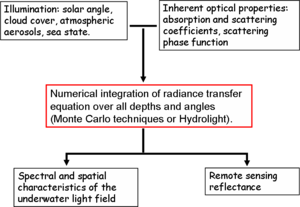
where L*(z,q,f) represents the gain in radiance due to light scattered from adjacent paths and S(z,q,f) accounts for any internal sources. In coastal waters, the most important internal source terms arise from Raman scattering by water molecules and fluorescence from dissolved organic matter and phytoplankton pigments. For light-field modelling the radiative transfer equation is solved numerically using either Monte Carlo methods or more conceptually sophisticated mathematical techniques (Mobley 1994[2], Thomas and Stamnes 1999[15]). The discrete ordinates method is commonly used in optical oceanography and is implemented in the commercially available Hydrolight software package (Sequoia Scientific). In order to construct a light field model, it is necessary to specify the nature of the input illumination, the IOPs of the medium, and any internal source functions (Figure 2). Light field models can generate a complete set of radiance values, but their output is usually summarised as a set of AOPs and reflectances which corresponds to those most frequently measured.
Optical closure
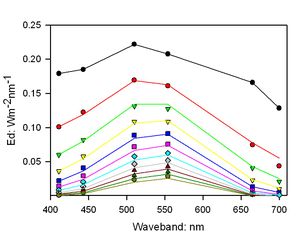
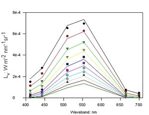
Ideally, it should be possible to construct a light field model of a coastal water column using measured values of the IOPs which would precisely replicate radiometric measurements made at the same time. This is known as ‘optical closure’. It is difficult to achieve in practice for two main reasons. First, it places great demands on the appropriate calibration and deployment of the measuring instruments. Second, some key IOPs such as the scattering phase function are difficult to measure in situ, and are usually estimated from the backscattering ratio (bb/b) using analytical functions. Figure 3 shows a typical attempt to achieve optical closure for a shelf sea station. In this instance the match between measured and modelled Ed values is reasonably good, but the Lu plots diverge significantly below 5 m.
Optical measurements in coastal waters
Submersible instruments are available from several specialist manufacturers, generally small companies established by researchers who have themselves made significant contributions to the field. Examples include WET Labs, HobiLabs and Bioshperical Instruments in the US, Satlantic in Canada and Trios in Germany.
Sensor deployment issues
Autonomous operation
Many instruments can be configured for autonomous operation with a data logger or for direct readout through a connecting cable. Autonomous operation usually makes deployment from ships more convenient and is obviously required on moorings. On the other hand, a connecting cable provides real-time monitoring and control of measurements and can also be used to provide electrical power.
Profiling measurements
Sensors mounted in an open protective frame can be lowered on a cable from a research vessel, but it can be difficult to maintain depth and orientation with sufficient precision when the ship moves in a swell. For radiometric measurements, it is particularly important to avoid the perturbing effects of the shadow of the ship or mooring structure on the underwater light field. These effects can be minimised by positioning the vessel so that the lowering location is facing into the sun, and by using an extended boom where possible. Free-fall packages connected to the ship by a loose cable have a number of advantages: they can be adjusted to fall at a predetermined velocity, are decoupled from ship motions, and can usually be moved some distance from the ship by relative motion imparted by tide or wind.
Moorings
Optical sensors generally have low power requirements and can be deployed for long periods from fixed moorings. However in coastal waters problems with fouling of optical windows and light paths are frequently encountered. Some manufacturers supply sensors fitted with copper shields or intake tubes, and occasionally with mechanical wipers for windows, but a fully reliable solution has yet to be demonstrated.
Radiometric measurements
Submersible sensors are available for planar and scalar irradiance measurements, using flat and spherical diffusers, and for radiance measurements with typical acceptance angles of 5-10o. It is useful to distinguish between different classes of radiance and irradiance meters based on their spectral resolution. PAR sensors have a single detector and a filter whose absorption characteristics are adjusted to provide the required quantum response from 400-700 nm. Multi-waveband sensors use individual photodiode and filter combinations for each channel, and typically have bandwidths of the order of 10 nm. High resolution (sometimes called hyperspectral) sensors employ miniature spectrographs and silicon detector arrays, and can have spectral resolutions of the order of a few nanometers. The sensitivity of a radiometric sensor is largely determined by size of the detecting element, typically square millimetres for a multi-waveband sensor and square microns for a high resolution sensor. Consequently high resolution sensors generally have limited sensitivity, which can limit their use as profiling instruments in coastal conditions.
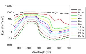
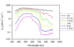
Figures 4 and 5 show typical measurements of light field profiles in the Bristol Channel and Irish Sea. The most obvious feature of both plots is the rapid loss with depth of blue wavelengths due to absorption by CDOM and MSS and of red wavelengths due to absorption by water. The increased attenuation in the Bristol Channel is due mainly to mineral particles in suspension.
Inherent Optical Property measurements
Instrumentation
The total coefficients of absorption (a) and attenuation (c) can be obtained using dual tube spectrophotometers which come in 9-waveband and continuous spectral versions (Wetlabs). Total scattering coefficients are then calculated from the difference of the two measured variables. Several instruments for measuring backscattering coefficients are available, including the Hydroscat series from Hobilabs and the ECO BB and VSF series from WET Labs. Backscattering measurements are made at one or more fixed angles and extrapolated using an assumed phase function to give a value for the entire backward hemisphere. The effect of attenuation on the signals measured by backscattering meters has to be explicitly taken into account. Nearly all instruments have limitations in their range of linear response, and this can pose problems in turbid coastal waters.
IOP Partitioning
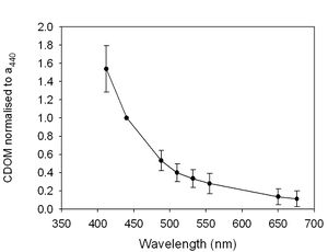
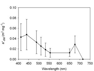
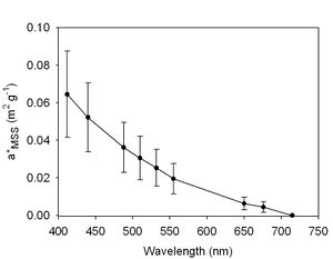
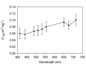
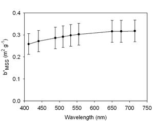
Partitioning of in situ measurements of total IOPs into the contributions of different classes of optically significant material usually requires ancillary measurements. The proportion of the total absorption coefficient due to dissolved material can be determined by filtering water samples through a 0.2 μm membrane filter. Phytoplankton pigment absorption can be separated from detrital absorption by collecting suspended material on a glass fibre filter and bleaching or extracting the pigments. The greatest difficulty is the partitioning of the scattering and backscattering coefficients between phytoplankton and mineral particles. Since the two constituents cannot be physically separated, their contribution to scattering is usually estimated using statistical regression techniques. The calculation of absorption coefficients for materials collected on glass fibre filters requires the determination of a ‘path length amplification factor’. There are several published approaches to determining this factor, and the most widely adopted is probably that of Bricaud and Stramski (1990[16]). It is also possible to determine the conversion factors empirically by direct comparison with ac-9 measurements carried out at the position from which the sample was taken. Figures 6 and 7 show the results obtained using these procedures for a data set acquired in the Irish Sea, Bristol Channel and Scottish west coast waters.
Regional characteristics
There are strong regional variations in the light fields of coastal waters, and also temporal patterns which may arise from enhanced mixing during the winter months or seasonal changes in freshwater run-off. Estuaries and shallow tidal areas often have optical properties dominated by suspended sediment, with shallow euphotic depths and high blue light attenuation. Areas with high freshwater inputs, including fjords and the Baltic Sea, generally have high CDOM levels. This has interesting consequences for phytoplankton growth, since the reduced salinity creates a buoyant layer which promotes surface bloom development while the loss of light due to CDOM absorption inhibits growth deeper in the water column. In spite of relatively high turbidity levels, eutrophicated areas with sufficient tidal stirring such as the Dutch coast may support intense phytoplankton blooms for most of the spring and summer seasons.
Implications for remote sensing
In Case 1 waters, which are usually deep and free of terrestrial influence, variations in optical properties are linked to chlorophyll concentration. In Case 2 waters, which include most coastal regions, the concentrations of the optically significant constituents can vary independently of each other. Interpreting optical remote sensing signals from Case 2 waters is particularly challenging (see for example IOCCG Report No 3[17] and Miller et al, 2005[18]) and standard band ratio algorithms frequently produce erroneous results. The problem is exacerbated by the fact that the atmospheric correction algorithms used for marine remote sensing often assume zero reflectance in the near infra-red, and this may not be valid for turbid waters.
In optically shallow coastal areas (where the physical depth is less than 1/Kd), the reflectance of the sea bed can be detected by radiometers or lidar systems mounted on aircraft (see also Use of Lidar for coastal habitat mapping). This opens up possibilities of optical bathymetric mapping in regions which are not easily accessible to surface craft, and of habitat classification by optical remote sensing. In general, however, both shallow-water surveying and deep-water remote sensing in the coastal region require a more sophisticated approach than is employed in standard band-ratio algorithms. This is currently a very active research area. One promising approach is the development of spectral matching techniques, in which an observed water-leaving radiance spectrum is compared to a library of spectra calculated for different constituent concentrations and bottom reflectivity using radiative transfer modelling. The success of this approach depends on more extensive studies of the variability of specific IOPs in coastal waters.
See also
Internal links
- optical remote sensing
- general principles of optical and acoustical instruments
- Optical Laser diffraction instruments (LISST)
- Optical backscatter point sensor (OBS)
- Use of Lidar for coastal habitat mapping
Further reading
- Babin M and Stramski D 2002 Light absorption by aquatic particles in the near-infrared spectral region. Limnology and Oceanography 47:911-915
- Babin, M, Morel A, Fournier-Sicre V, Fell F and Stramski D 2003. Light scattering properties of marine particles in coastal and oceanic waters as related to the particle mass concentration. Limnology and Oceanography, 48, 843-859
References
- ↑ 1.0 1.1 1.2 Kirk J T O 1994 Light and photosynthesis in aquatic ecosystems. Cambridge University Press, Cambridge, 410 pp.
- ↑ 2.0 2.1 2.2 Mobley C D 1994 Light and water; radiative transfer in natural waters. Academic Press, San Diego, 592pp. ISBN 0125027508
- ↑ Bukata R P, Jerome J H , Kondratyev K Y and Pozdnyakov D V 1995 Optical properties and remote sensing of inland and coastal waters. CRC Press, 384pp
- ↑ DeCusatis C M (ed) 1997 Handbook of Applied Photometry. American Institute of Physics Press, New York, 484 pp.
- ↑ Bricaud A, Morel A and Prieur L 1981 Absorption by dissolved organic matter of the sea (yellow substance) in the UV and visible domains. Limnology and Oceanography 26:43-53.
- ↑ Babin M., and Stramski D 2005 Variations in the mass-specific absorption coefficient of mineral particles suspended in water. Limnology and Oceanography, 49, 756-767
- ↑ Wozniak, Slawomir B.; Stramski, Dariusz 2004 Modeling the Optical Properties of Mineral Particles Suspended in Seawater and their Influence on Ocean Reflectance and Chlorophyll Estimation from Remote Sensing Algorithms Applied Optics IP, vol. 43, Issue 17, pp.3489-3503
- ↑ Sathyendranath S, Lazzara L, Prieur L 1987 Variations in the Spectral Values of Specific Absorption of Phytoplankton. Limnology and Oceanography 32: 403-415
- ↑ Bricaud, A., Bedhomme, A.L. and A. Morel (1988). Optical properties of diverse phytoplanktonic species: Experimental results and theoretical interpretation, Journal of Plankton Research, 10, 851-873
- ↑ Johnsen G, Samset O, Grauskog L and Sakshaug E 1994 In vivo absorption characteristics in 10 classes of bloom-forming phytoplankton: taxonomic characteristics and responses to photoadaptation by means of discriminant and HPLC analysis. Marine Ecology Progress Series 105:149-157
- ↑ Quirantes A and Bernard S 2004 Light scattering by marine algae: two-layer spherical and nonspherical models. Journal of Quantitative Spectroscopy & Radiative Transfer 89: 311–321
- ↑ Volten H, de Haan J F , Hovenier J W, Scheurs R, Vassen W, Dekker A G, Hoogenboom H J, Charlton F and Wouts R. 1998 Laboratory measurements of angular distributions of light scattered by phytoplankton and silt. Limnology and Oceanography 43: 1180-1197.
- ↑ Zaneveld J R V and Pegau W S 2003 Robust underwater visibility parameter. Optics Express 11:2997-3009
- ↑ Goody R M and Yung Y L 1989 Atmospheric radiation, theoretical basis. Oxford University Press, Oxford. 519pp.
- ↑ Thomas G E.and Stamnes K 1999 Radiative transfer in the atmosphere and ocean, Cambridge, New York, Cambridge University Press 517 p., ISBN 0521401240.
- ↑ Bricaud A and Stramski D 1990 Spectral absorption coefficients of living phytoplankton and nonalgal biogenous matter: A comparison between the Peru upwelling area and the Sargasso Sea. Limnol. Oceanogr., 35(3), 1990, 562-582
- ↑ IOCCG 2000 Remote sensing of ocean colour in coastal, and other optically complex waters. Sathyendranath, S (ed) Reports of the International Ocean-Colour Coordinating Group No. 3, IOCCG, Dartmouth, Canada.
- ↑ Miller R, Del-Castillo C and McKee B (eds) 2005 Remote sensing of coastal aquatic environments. Springer, Dordrecht 347p
Please note that others may also have edited the contents of this article.
|
Please note that others may also have edited the contents of this article.
|

