Difference between revisions of "Sand by-pass systems"
(→Introduction) |
Dronkers J (talk | contribs) |
||
| (49 intermediate revisions by 2 users not shown) | |||
| Line 1: | Line 1: | ||
| + | {{ | ||
| + | Definition|title= Sand by-pass system|definition= A Sand Bypass System is a permanent solution to sand erosion and littoral drift problems affecting river mouths and navigation channels worldwide. It is described as the artificial transport of littoral drift across tidal entrances to help prevent accretion, on the updrift side, control downdrift erosion and maintain navigation channels.}} | ||
| + | |||
| + | |||
== Introduction == | == Introduction == | ||
<p> | <p> | ||
Figs. 1 and 2 show two examples of pure natural stretches of sandy coasts. Fig. 1 reflects just a sandy coast with a net alongshore sediment transport.<p> | Figs. 1 and 2 show two examples of pure natural stretches of sandy coasts. Fig. 1 reflects just a sandy coast with a net alongshore sediment transport.<p> | ||
| − | Fig. 2 deals with a situation where a modest river flows out into the sea. Along the coast a net sediment transport is present in the right direction. In Fig. 2 two situations have been sketched; the present situation and the situation after a couple of years. Due to the river discharge and the net sediment transport at sea, the position of the mouth of the river shifts in the right direction with time. A long spit is formed between the sea and the left bank of the river. The river flows for some distance more or less parallel to the coastline. This process of shifting of the mouth of the river will not continue for ever. When the river becomes longer and longer the water level, say in point P in the river becomes higher and higher. At a certain moment the spit will break (at point P in the discussion) and a new mouth is formed farther upstream; the old mouth will close. The shift of the mouth resumes again; it is cyclic process with time. | + | Fig. 2 deals with a situation where a modest river flows out into the sea. Along the coast a net sediment transport is present in the right direction. In Fig. 2 two situations have been sketched; the present situation and the situation after a couple of years. Due to the river discharge and the net sediment transport at sea, the position of the mouth of the river shifts in the right direction with time. A long [[sand spit]] is formed between the sea and the left bank of the river. The river flows for some distance more or less parallel to the coastline. This process of shifting of the mouth of the river will not continue for ever. When the river becomes longer and longer the water level, say in point P in the river becomes higher and higher. At a certain moment the [[sand spit]] will break (at point P in the discussion) and a new mouth is formed farther upstream; the old mouth will close. The shift of the mouth resumes again; it is cyclic process with time. |
<p> | <p> | ||
<br> | <br> | ||
| Line 33: | Line 37: | ||
<br> | <br> | ||
<p> | <p> | ||
| − | == Solution with sand bypass system == | + | == Solution with sand by-pass system == |
| + | Fig. 5 shows that a large port with two long breakwaters has been built indeed along the sandy coast. | ||
| + | In Fig. 6 the position of the mouth of the river has been stabilized with the help of two jetties. In selecting the position where the jetties are built, the cyclic process of the shifting position of the mouth of the river should be taken into account. A position in the beginning of the cyclic process is recommended. | ||
| + | <p> | ||
| + | In both cases of Figs. 5 and 6 the long breakwaters/jetties interrupt the sediment transport along the sandy coast. The classical processes of accretion of sediment at the up drift side of the structures and the erosion at the down drift side will start right after the construction. Fig. 7 shows schematically what happens in case of a single jetty which interrupts the sediment transport. At the seaward end of the long jetty no sediment will pass the jetty (for the time being); accumulation of sand will occur at the up drift side. At some distance from the jetty at the down drift side the sediment transport along the coast is again the same as the original sediment transport at the up drift side (Sout = Sin). The down drift part of the coast does not receive sediment (S = 0) along the jetty, while Sout leaves that part. Structural erosion will occur. | ||
| + | <p> | ||
| + | <br> | ||
| + | <p> | ||
| + | {| style ="margin-left: 1em" align="center" style="text-align:center; font-size:85%" | ||
| + | |[[Image:Sand bypass Slide5.JPG|325px]] | ||
| + | |[[Image:Sand bypass Slide6.JPG|330px]] | ||
| + | |- | ||
| + | |Valign="top"| '''Fig. 5 Port for export of ore''' | ||
| + | |Valign="top"| '''Fig. 6 Position of mouth of river fixed''' | ||
| + | |- | ||
| + | |[[Image:Sand bypass Slide7.JPG|325px]] | ||
| + | |[[Image:Sand bypass Slide8.JPG|325px]] | ||
| + | |- | ||
| + | |Valign="top"| '''Fig. 7 Accretion and erosion''' | ||
| + | |Valign="top"| '''Fig. 8 Idea of sand by-passing''' | ||
| + | |} | ||
| + | <p> | ||
| + | <br> | ||
| + | <p> | ||
| + | ===Accretion=== | ||
| + | <p> | ||
| + | In some cases the [[accretion]] at the up drift side is not felt as a problem for the coastal zone manager; valuable ‘new’ land is created. (However, sooner or later the accretion of the coast reaches the seaward end of the jetty. Sediment will pass the structure. One of the main functions of the structures, stopping the sediment transport, is then not fulfilled anymore.) | ||
| + | <p> | ||
| + | <br> | ||
| + | <p> | ||
| + | |||
| + | ===Erosion=== | ||
| + | <p> | ||
| + | The consequences of the process of [[erosion]] at the down drift side are almost always a big problem. Ultimately mainland is lost. When the port like in Fig. 5 was built in a really inhospitable remote area, the erosion of ‘worthless’ land might be acceptable at a first glance. However, even a port mainly meant for the export of ore will attract a lot of other economic development. Rather soon the whole area will be booming; the ‘worthless’ land will become valuable. | ||
| + | So, the structural erosion at the down drift side is a problem which has to be resolved by the responsible coastal zone manager involved. | ||
| + | Often the erosion problem is seen as a separate problem; elsewhere along the coast also eroding stretches are observed. With ‘hard’ measures, e.g. [[groynes]], shore parallel detached breakwaters, and even seawalls and revetments, the erosion is tackled. (Seawalls and revetments are by the way a very bad solution for this type of erosion.) In stead of ‘hard’ measures, and often far better, ‘soft’ measures like [[shore nourishment]]s will be used. | ||
| + | <p> | ||
| + | The rate of the sediment transport along the coast determines for a great part how serious the accretion and erosion problems are in the vicinity of the structures. Whether the sediment transport is e.g. 100,000 m³/year or 500,000 m³/year makes a great deal of difference. | ||
| + | <p> | ||
| + | <br> | ||
| + | <p> | ||
| + | |||
| + | ===Sand by-passing=== | ||
| + | <p> | ||
| + | The most straightforward solution for the erosion problem (and the [[accretion]] problem) is to artificially restore the sediment transport along the structures as meant in the Figs. 5 and 6; applying a sand by-pass system. | ||
| + | Fig. 8 schematically shows this idea. The idea of artificial sand by-passing is so straightforward and seems so self-evident that it is remarkable that in practice this idea is applied in only a relatively small number of cases. | ||
| + | It is a good thing that nowadays coastal zone managers and coastal engineers have an open mind with respect to the (often: adverse) consequences of building breakwaters and jetties to the morphological system. Sand by-pass systems are a good tool now. | ||
| + | <p> | ||
| + | <br> | ||
| + | <p> | ||
| + | |||
| + | == ‘Problems’ with respect to the application of sand by-pass systems == | ||
| + | <p> | ||
| + | There are some obvious reasons why (in the past) so less sand by-pass systems have been applied in practice. These reasons are still present and play an import role in the design process of a proper by-pass system. Some remarks are made in this respect. | ||
| + | <p> | ||
| + | <br> | ||
| + | <p> | ||
| + | ===Accretion and erosion=== | ||
| + | <p> | ||
| + | As said the ‘new’ land at the up drift side of the structures is often cordially welcomed. New land close to the sea offers good opportunities for (urban) development. In case of a port it can even be used to extent the port area in future. It is then felt as a missing chance to remove the accreted sand and by-pass it.<br> | ||
| + | The erosion at the down drift side is then considered as a separate problem which has to be resolved with proper counter measures. | ||
| + | <p> | ||
| + | <br> | ||
| + | <p> | ||
| + | ===Rate of yearly sediment transport along the coast=== | ||
| + | <p> | ||
| + | In the past it often occurred that one was hardly able to properly estimate the yearly sediment transport along the coast. However, it was felt that good reasons were present to anyhow build a port or to anyhow build jetties at a river mouth. Construct and see what happens. In some cases it turned out that the rate of yearly sediment transport was so large (e.g. ≈ 1,000,000 m³/per year) that rather soon (unexpected) big problems came up. | ||
| + | For the design of a proper by-pass system one must know what the average yearly capacity of the system should by. (Compare the earlier remark whether 100,000 m³/year or 500,000 m³/year is the transport rate along the coast.) | ||
| + | <p> | ||
| + | <br> | ||
| + | <p> | ||
| + | ===Construct port/jetties and estimate afterwards the rate of sediment transport=== | ||
| + | ''A bypass system can be applied later on'' | ||
| + | <p> | ||
| + | Monitoring for some years the actual rate of accretion at the up drift side is of course a perfect method to estimate the apparent yearly sediment transport along the coast. With this knowledge a proper design of a by-pass system could be made. It is in some cases a draw-back that only after a couple of years after the construction of for instance a port, a sand by-pass system can be properly designed. Building a new port calls for a large investment; a proper by-pass system forms in fact a minor part of the total investment. However, if the by-pass system becomes operational many years after the construction of the port additional funds must be found and formal responsibilities must be settled. | ||
| + | <p> | ||
| + | <br> | ||
| + | <p> | ||
| + | |||
| + | == Some sand by-pass possibilities == | ||
| + | <p> | ||
| + | ===Sea-route=== | ||
| + | <p> | ||
| + | In Fig. 8 a land-route and a sea-route have been sketched. | ||
| + | The sea-route seems attractive at a first glance. Existing tools (hopper dredges) can be used; the capacity of the system is easy to adjust. In practice it is, however, very difficult to dredge somewhere in the accretion area. The occurring sediment transport is often confined to a rather small zone close to the waterline. So that forces the dredge in fact to operate in rather shallow water with often wave action. If the dredge would operate at somewhat deeper water, the input of arriving sand from the up drift side to the dredged area is not assured. | ||
| + | In some cases the accretion of sediment in the up drift side has reached the seaward end of the structures already, causing sedimentation in the entrance channel. ‘Maintenance’ dredging of the channel is then often necessary. Dumping of the dredged material at the down drift side seems obvious. | ||
| + | <p> | ||
| + | The [[erosion]] process in the down drift area is clearly visible in the upper parts of the cross-shore profiles. The (gradient of the) sediment transport along the coast takes mainly place in the upper parts of the coastal profile indeed. Dumping of (by-passed) sand must happen at not too large water depths. By cross-shore sediment transports sand might be moved from deeper water to the shoreline (where it is needed in fact), but if the dumping area is too deep, too less sediment will be moved landward. | ||
| + | <p> | ||
| + | <br> | ||
| + | <p> | ||
| + | |||
| + | ===Land-route=== | ||
| + | <p> | ||
| + | When the needed by-pass volume is rather small, a simple system with the help of trucks might be considered. (A volume of for example 50,000 m³/year, to be transported by trucks with a capacity of 15 m³ in 200 working days per year, results in 17 truck-trips every working day!) The system with trips by trucks around a port is rather easy; trips around a river mouth with jetties are only feasible if a bridge over the river is present close to the sea. | ||
| + | <p> | ||
| + | In most cases a permanent pipeline is used to transport the sand (as slurry) from the one side to the other. In case of a river the pipeline crosses the river at the bottom. At the discharge end of the pipeline often a few different discharge positions along the eroding coast can be used by choice. | ||
| + | <p> | ||
| + | To get the sand ‘into the pipeline’ in the up drift area, is a special point of concern. The basic problem is that a more or less continuous process of catching the arriving sand along the coast must be assured. The system with a gap in the up drift breakwater in order to catch the up coming sand and to create a quiet area for a (small) dredge (see Fig. 9) has been tried in the past, but was not a success. <br> | ||
| + | The system as meant in Fig. 10 with an additional offshore breakwater to create a quiet area has more possibilities, but also in this case a continuous inflow of sediment in the catchment area is not for sure. | ||
| + | <p> | ||
| + | Fig. 11 shows schematically a system which is applied more and more nowadays. A trestle perpendicular to the coast, high above the water level at sea, covers the beach and a part of the cross-section towards deeper water (farther than the width of the surf zone). On top of the trestle a suction device with a suction pipe is able to move over the trestle. The suction device creates a channel perpendicular to the coast. This channel catches the up coming sand.<p> | ||
| + | Fig. 12 shows a picture of the trestle of the Tweed River sand by-pass system in Australia. This Tweed River system has a capacity of about 500,000 m³ per year. The sand can be released at 4 different points<ref>Boswood, P.K., Voisey, C.J., Victory, S.J., Robinson, D.A., Dyson, A.R. and Lawson, S.R. 2005. Beach Response to Tweed River Entrance Sand Bypassing Operations. Conference Australasian Coasts and Ports 2005, Adelaide, South Australia</ref> | ||
| + | <p> | ||
| + | <br> | ||
| + | <p> | ||
| + | {| style ="margin-left: 1em" align="center" style="text-align:center; font-size:85%" | ||
| + | |[[Image:Sand bypass Slide9.JPG|325px]] | ||
| + | |[[Image:Sand bypass Slide10.JPG|325px]] | ||
| + | |- | ||
| + | |Valign="top"| '''Fig. 9 Port with gap in breakwater''' | ||
| + | |Valign="top"| '''Fig. 10 Port with additional offshore breakwater''' | ||
| + | |- | ||
| + | |colspan="2" Align="center"|[[Image:Sand bypass Slide11.JPG|325px]] | ||
| + | |- | ||
| + | |colspan="2"|'''Fig. 11 Port with trestle''' | ||
| + | |- | ||
| + | |colspan="2"|[[Image:Trestle of Tweed River Sand bypass system.jpg|650px]] | ||
| + | |- | ||
| + | |colspan="2"|'''Fig. 12 Trestle of Tweed River Sand bypass system''' <br> ''from: website of [http://www.tweedsandbypass.nsw.gov.au/ Tweed River project]'' | ||
| + | |} | ||
| + | <p> | ||
| + | |||
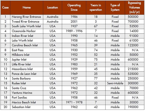
| + | [[Image:SandBypassingSystemsInventory2008.jpg|600px|thumbnail|center|Figure 13. Inventory (2008) of sand bypass systems <ref>Loza, P. 2008. Sand Bypassing systems. Master thesis Environmental Engineering, Porto University (PT)</ref>.]] | ||
| + | |||
| + | |||
| + | ==References== | ||
| + | <references/> | ||
| + | |||
| + | |||
| + | ==Further reading== | ||
| + | |||
| + | Boswood, P.K. and Murray, R.J. 2001. World-wide Sand Bypassing Systems: Data Report (Compiled 1997). Queensland | ||
| + | Government Environmental Protection Agency, Conservation Technical Report 15 | ||
| + | |||
| + | |||
| + | |||
| + | <p> | ||
| + | <br> | ||
| + | <p> | ||
| + | == See Also == | ||
| + | <p> | ||
| + | * [[Shore nourishment]] | ||
| + | * [[erosion]] | ||
| + | * [[Application of breakwaters]] | ||
| + | * [[Port breakwaters and coastal erosion]] | ||
| + | * [[Coastal management]] | ||
| + | * [[Dealing with coastal erosion]] | ||
| + | * [[Manual Sediment Transport Measurements in Rivers, Estuaries and Coastal Seas]] | ||
| + | * [http://www.tweedsandbypass.nsw.gov.au/ Tweed River Entrance Sand Bypassing Project] | ||
| + | |||
| + | <p> | ||
| + | <br> | ||
| + | <p> | ||
| + | {{Authorwithoutaccount | ||
| + | |AuthorID=11540 | ||
| + | |AuthorFullName=van de Graaff, Jan}} | ||
| + | |||
| + | [[Category:Coastal protection]] | ||
| + | [[Category:Hard structures]] | ||
| + | [[Category:Soft coastal interventions]] | ||
Latest revision as of 17:13, 18 January 2022
Definition of Sand by-pass system:
A Sand Bypass System is a permanent solution to sand erosion and littoral drift problems affecting river mouths and navigation channels worldwide. It is described as the artificial transport of littoral drift across tidal entrances to help prevent accretion, on the updrift side, control downdrift erosion and maintain navigation channels.
This is the common definition for Sand by-pass system, other definitions can be discussed in the article
|
Contents
Introduction
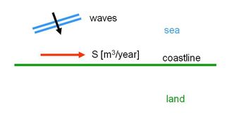
Figs. 1 and 2 show two examples of pure natural stretches of sandy coasts. Fig. 1 reflects just a sandy coast with a net alongshore sediment transport.
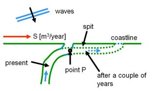
Fig. 2 deals with a situation where a modest river flows out into the sea. Along the coast a net sediment transport is present in the right direction. In Fig. 2 two situations have been sketched; the present situation and the situation after a couple of years. Due to the river discharge and the net sediment transport at sea, the position of the mouth of the river shifts in the right direction with time. A long sand spit is formed between the sea and the left bank of the river. The river flows for some distance more or less parallel to the coastline. This process of shifting of the mouth of the river will not continue for ever. When the river becomes longer and longer the water level, say in point P in the river becomes higher and higher. At a certain moment the sand spit will break (at point P in the discussion) and a new mouth is formed farther upstream; the old mouth will close. The shift of the mouth resumes again; it is cyclic process with time.
|
|
| Fig. 1: Natural situation | Fig. 2: Natural situation; free development |
|
|
| Fig. 3 Ore found | Fig. 4 Situation with roads and houses/hotels |
The coastal processes as meant in Figs.1 and 2 occurred without human involvements for thousands of years.
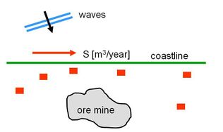
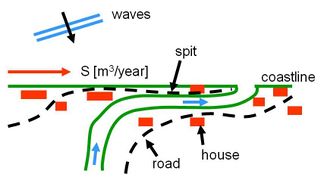
Figs. 3 and 4 show the same cases as Figs. 1 and 2, but now with human interests. These human interests have become more and more relevant during say the last hundred years only. In the example of Fig. 3 ore has been found close to the coast; export of ore is a big opportunity for the economy; a large sea-port is required. Fig. 4 shows a situation where infrastructure like roads and buildings has been built in the coastal area. Often the river mouth is also used for navigation. The ever changing position of the mouth of the river is a serious draw-back in this area. One often likes to stabilize the position of the river mouth.
In stead of a port and a river mouth, used in this contribution as examples, also a tidal inlet of a lagoon could be chosen; similar considerations as given so far hold in that case.
Solution with sand by-pass system
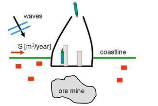
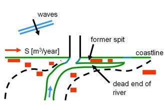
Fig. 5 shows that a large port with two long breakwaters has been built indeed along the sandy coast. In Fig. 6 the position of the mouth of the river has been stabilized with the help of two jetties. In selecting the position where the jetties are built, the cyclic process of the shifting position of the mouth of the river should be taken into account. A position in the beginning of the cyclic process is recommended.
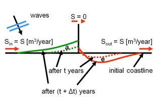
In both cases of Figs. 5 and 6 the long breakwaters/jetties interrupt the sediment transport along the sandy coast. The classical processes of accretion of sediment at the up drift side of the structures and the erosion at the down drift side will start right after the construction. Fig. 7 shows schematically what happens in case of a single jetty which interrupts the sediment transport. At the seaward end of the long jetty no sediment will pass the jetty (for the time being); accumulation of sand will occur at the up drift side. At some distance from the jetty at the down drift side the sediment transport along the coast is again the same as the original sediment transport at the up drift side (Sout = Sin). The down drift part of the coast does not receive sediment (S = 0) along the jetty, while Sout leaves that part. Structural erosion will occur.
|
|
| Fig. 5 Port for export of ore | Fig. 6 Position of mouth of river fixed |
|
|
| Fig. 7 Accretion and erosion | Fig. 8 Idea of sand by-passing |
Accretion
In some cases the accretion at the up drift side is not felt as a problem for the coastal zone manager; valuable ‘new’ land is created. (However, sooner or later the accretion of the coast reaches the seaward end of the jetty. Sediment will pass the structure. One of the main functions of the structures, stopping the sediment transport, is then not fulfilled anymore.)
Erosion
The consequences of the process of erosion at the down drift side are almost always a big problem. Ultimately mainland is lost. When the port like in Fig. 5 was built in a really inhospitable remote area, the erosion of ‘worthless’ land might be acceptable at a first glance. However, even a port mainly meant for the export of ore will attract a lot of other economic development. Rather soon the whole area will be booming; the ‘worthless’ land will become valuable. So, the structural erosion at the down drift side is a problem which has to be resolved by the responsible coastal zone manager involved. Often the erosion problem is seen as a separate problem; elsewhere along the coast also eroding stretches are observed. With ‘hard’ measures, e.g. groynes, shore parallel detached breakwaters, and even seawalls and revetments, the erosion is tackled. (Seawalls and revetments are by the way a very bad solution for this type of erosion.) In stead of ‘hard’ measures, and often far better, ‘soft’ measures like shore nourishments will be used.
The rate of the sediment transport along the coast determines for a great part how serious the accretion and erosion problems are in the vicinity of the structures. Whether the sediment transport is e.g. 100,000 m³/year or 500,000 m³/year makes a great deal of difference.
Sand by-passing
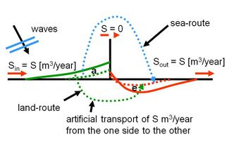
The most straightforward solution for the erosion problem (and the accretion problem) is to artificially restore the sediment transport along the structures as meant in the Figs. 5 and 6; applying a sand by-pass system. Fig. 8 schematically shows this idea. The idea of artificial sand by-passing is so straightforward and seems so self-evident that it is remarkable that in practice this idea is applied in only a relatively small number of cases. It is a good thing that nowadays coastal zone managers and coastal engineers have an open mind with respect to the (often: adverse) consequences of building breakwaters and jetties to the morphological system. Sand by-pass systems are a good tool now.
‘Problems’ with respect to the application of sand by-pass systems
There are some obvious reasons why (in the past) so less sand by-pass systems have been applied in practice. These reasons are still present and play an import role in the design process of a proper by-pass system. Some remarks are made in this respect.
Accretion and erosion
As said the ‘new’ land at the up drift side of the structures is often cordially welcomed. New land close to the sea offers good opportunities for (urban) development. In case of a port it can even be used to extent the port area in future. It is then felt as a missing chance to remove the accreted sand and by-pass it.
The erosion at the down drift side is then considered as a separate problem which has to be resolved with proper counter measures.
Rate of yearly sediment transport along the coast
In the past it often occurred that one was hardly able to properly estimate the yearly sediment transport along the coast. However, it was felt that good reasons were present to anyhow build a port or to anyhow build jetties at a river mouth. Construct and see what happens. In some cases it turned out that the rate of yearly sediment transport was so large (e.g. ≈ 1,000,000 m³/per year) that rather soon (unexpected) big problems came up. For the design of a proper by-pass system one must know what the average yearly capacity of the system should by. (Compare the earlier remark whether 100,000 m³/year or 500,000 m³/year is the transport rate along the coast.)
Construct port/jetties and estimate afterwards the rate of sediment transport
A bypass system can be applied later on
Monitoring for some years the actual rate of accretion at the up drift side is of course a perfect method to estimate the apparent yearly sediment transport along the coast. With this knowledge a proper design of a by-pass system could be made. It is in some cases a draw-back that only after a couple of years after the construction of for instance a port, a sand by-pass system can be properly designed. Building a new port calls for a large investment; a proper by-pass system forms in fact a minor part of the total investment. However, if the by-pass system becomes operational many years after the construction of the port additional funds must be found and formal responsibilities must be settled.
Some sand by-pass possibilities
Sea-route
In Fig. 8 a land-route and a sea-route have been sketched. The sea-route seems attractive at a first glance. Existing tools (hopper dredges) can be used; the capacity of the system is easy to adjust. In practice it is, however, very difficult to dredge somewhere in the accretion area. The occurring sediment transport is often confined to a rather small zone close to the waterline. So that forces the dredge in fact to operate in rather shallow water with often wave action. If the dredge would operate at somewhat deeper water, the input of arriving sand from the up drift side to the dredged area is not assured. In some cases the accretion of sediment in the up drift side has reached the seaward end of the structures already, causing sedimentation in the entrance channel. ‘Maintenance’ dredging of the channel is then often necessary. Dumping of the dredged material at the down drift side seems obvious.
The erosion process in the down drift area is clearly visible in the upper parts of the cross-shore profiles. The (gradient of the) sediment transport along the coast takes mainly place in the upper parts of the coastal profile indeed. Dumping of (by-passed) sand must happen at not too large water depths. By cross-shore sediment transports sand might be moved from deeper water to the shoreline (where it is needed in fact), but if the dumping area is too deep, too less sediment will be moved landward.
Land-route
When the needed by-pass volume is rather small, a simple system with the help of trucks might be considered. (A volume of for example 50,000 m³/year, to be transported by trucks with a capacity of 15 m³ in 200 working days per year, results in 17 truck-trips every working day!) The system with trips by trucks around a port is rather easy; trips around a river mouth with jetties are only feasible if a bridge over the river is present close to the sea.
In most cases a permanent pipeline is used to transport the sand (as slurry) from the one side to the other. In case of a river the pipeline crosses the river at the bottom. At the discharge end of the pipeline often a few different discharge positions along the eroding coast can be used by choice.
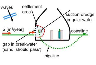
To get the sand ‘into the pipeline’ in the up drift area, is a special point of concern. The basic problem is that a more or less continuous process of catching the arriving sand along the coast must be assured. The system with a gap in the up drift breakwater in order to catch the up coming sand and to create a quiet area for a (small) dredge (see Fig. 9) has been tried in the past, but was not a success.
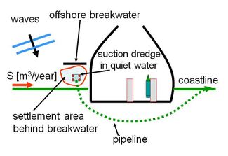
The system as meant in Fig. 10 with an additional offshore breakwater to create a quiet area has more possibilities, but also in this case a continuous inflow of sediment in the catchment area is not for sure.
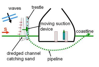
Fig. 11 shows schematically a system which is applied more and more nowadays. A trestle perpendicular to the coast, high above the water level at sea, covers the beach and a part of the cross-section towards deeper water (farther than the width of the surf zone). On top of the trestle a suction device with a suction pipe is able to move over the trestle. The suction device creates a channel perpendicular to the coast. This channel catches the up coming sand.
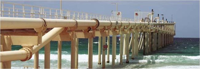
Fig. 12 shows a picture of the trestle of the Tweed River sand by-pass system in Australia. This Tweed River system has a capacity of about 500,000 m³ per year. The sand can be released at 4 different points[1]
|
|
| Fig. 9 Port with gap in breakwater | Fig. 10 Port with additional offshore breakwater |
| |
| Fig. 11 Port with trestle | |
| |
| Fig. 12 Trestle of Tweed River Sand bypass system from: website of Tweed River project | |
References
- ↑ Boswood, P.K., Voisey, C.J., Victory, S.J., Robinson, D.A., Dyson, A.R. and Lawson, S.R. 2005. Beach Response to Tweed River Entrance Sand Bypassing Operations. Conference Australasian Coasts and Ports 2005, Adelaide, South Australia
- ↑ Loza, P. 2008. Sand Bypassing systems. Master thesis Environmental Engineering, Porto University (PT)
Further reading
Boswood, P.K. and Murray, R.J. 2001. World-wide Sand Bypassing Systems: Data Report (Compiled 1997). Queensland Government Environmental Protection Agency, Conservation Technical Report 15
See Also
- Shore nourishment
- erosion
- Application of breakwaters
- Port breakwaters and coastal erosion
- Coastal management
- Dealing with coastal erosion
- Manual Sediment Transport Measurements in Rivers, Estuaries and Coastal Seas
- Tweed River Entrance Sand Bypassing Project
Please note that others may also have edited the contents of this article.
|